General Principles & Introduction to Statics
Fundamental Concepts, Idealizations, Newton's Laws, and Systems of Units
The primary objective of this book is to provide a clear, comprehensive, and modern introduction to the theory and application of engineering mechanics. As civil engineers, our foremost responsibility is to design structures—from towering skyscrapers to expansive bridges—that are safe, efficient, and capable of withstanding the forces of nature. To achieve this, an absolute mastery of the principles of statics is not just recommended; it is mandatory. In this opening chapter, we will introduce the fundamental concepts, the universal laws governing these principles, and the system of units we will employ throughout our analyses.
1.1 Mechanics and Statics
Mechanics is a branch of the physical sciences that is concerned with the state of rest or motion of bodies that are subjected to the action of forces. No other subject plays a greater role in engineering analysis. In general, this broad subject can be subdivided into three distinct branches: rigid-body mechanics, deformable-body mechanics, and fluid mechanics.
In this textbook, we will exclusively study rigid-body mechanics. This branch is logically divided into two parts:
Statics: Deals with the equilibrium of bodies, that is, those that are either at rest or moving with a constant velocity.
Dynamics: Deals with the accelerated motion of bodies.
We can consider statics as a special case of dynamics in which the acceleration is identically zero. However, statics deserves its own comprehensive treatment in civil engineering education, as the vast majority of our objects (buildings, bridges, dams) are designed with the strict intention that they remain in equilibrium.
1.2 Fundamental Concepts and Principles
Before we mathematically apply the principles of statics to solve engineering problems, it is crucial to clearly understand the basic quantities and idealizations that form our conceptual models.
1.2.1 Basic Quantities
Length: Used to locate the position of a point in space and thereby describe the size of a physical system.
Time: The measure of the succession of events. While time plays a critical role in dynamics, it is not directly involved in the analysis of statics problems.
Mass: A measure of a quantity of matter that is used to compare the action of one body with that of another. It provides a measure of the resistance of matter to a change in velocity.
Force: Considered as a "push" or "pull" exerted by one body on another. A force is completely characterized by its magnitude, direction, and point of application (a vector quantity).
1.2.2 Idealizations
Models or idealizations are used in mechanics to simplify the application of theory. We will frequently rely on the following three:
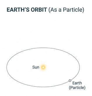
Particle: A particle has a mass, but its size can be neglected. For example, the Earth can be modeled as a particle when studying its orbital motion around the sun (Figure 1.2 and Figure 1.3).
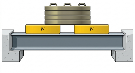
Rigid Body: A rigid body can be considered as a combination of a large number of particles in which all the particles remain at a fixed distance from one another, both before and after applying a load (Figure 1.4). Material deformations are assumed to be zero.
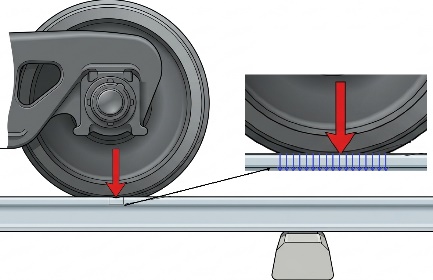
Concentrated Force: Represents the effect of a loading which is assumed to act at a specific mathematical point on a body (Figure 1.5, e.g., a wheel resting on a steel rail).

1.2.3 The Six Fundamental Principles of Mechanics
The entire subject of engineering mechanics is formulated on the basis of six fundamental principles. These principles have been established through centuries of experimental evidence and observation; they cannot be proven mathematically, making them the foundational axioms of physical science. Understanding these principles is absolutely critical before undertaking any structural analysis.
1. The Parallelogram Law for the Addition of Forces
This principle states that two forces acting simultaneously on a particle may be replaced by a single force, called a resultant, which is obtained by drawing the diagonal of the parallelogram which has sides equal to the given forces. This principle establishes that forces are vector quantities and must be added geometrically rather than algebraically.
2. The Principle of Transmissibility (and Superposition)
This principle states that the conditions of equilibrium or motion of a rigid body will remain unchanged if a force acting at a given point of the rigid body is replaced by a force of the same magnitude and same direction, but acting at a different point, provided that the two forces have the same line of action. In statics, this allows us to treat external forces as "sliding vectors" that can be moved along their line of action to simplify calculations.
3. Newton’s First Law of Motion
A particle originally at rest, or moving in a straight line with a constant velocity, will tend to remain in this state provided the particle is not subjected to an unbalanced force.
Significance in Statics: This is the governing law of our course. It dictates that for a structure to remain in static equilibrium, the resultant of all forces acting on it must be strictly zero (\(\sum \vec{F} = \vec{0}\)).
4. Newton’s Second Law of Motion
A particle acted upon by an unbalanced force \(\vec{F}\) experiences an acceleration \(\vec{a}\) that has the same direction as the force and a magnitude that is directly proportional to the force. Mathematically expressed as:
Significance in Statics: While this is the fundamental equation of dynamics, it proves our static condition: if a body is in equilibrium (acceleration \(\vec{a} = \vec{0}\)), then the sum of forces must be zero.
5. Newton’s Third Law of Motion
The mutual forces of action and reaction between two interacting bodies are equal in magnitude, opposite in direction, and collinear (they lie on the same line).
Significance in Statics: This principle is the cornerstone of drawing Free-Body Diagrams (FBDs). When we conceptually separate interconnected structural members (like beams and columns), the internal forces holding them together must be represented as equal and opposite reaction pairs.
6. Newton's Law of Gravitational Attraction
Shortly after formulating his three laws of motion, Sir Isaac Newton postulated a law governing the gravitational attraction between any two particles in the universe. It is expressed as:
where:
\(F\) is the mutual force of attraction between the two particles.
\(G\) is the universal constant of gravitation (\(3.439 \times 10^{-8}\text{ ft}^3/(\text{slug}\cdot\text{s}^2)\) or \(6.673 \times 10^{-11}\text{ m}^3/(\text{kg}\cdot\text{s}^2)\)).
\(m_1, m_2\) are the masses of the two particles.
\(r\) is the distance between the centers of the two particles.
Engineering Note: In civil engineering applications, the mutual attraction between two objects on Earth (like a concrete pier and a steel beam) is infinitesimally small and completely negligible. The only gravitational force we consider is the massive attraction between the Earth and the object, which we simply call the Weight (\(W = mg\)).
Example 1.1
Determine the weight in newtons of a steel beam whose mass is \(150\text{ slugs}\) on the surface of the earth. Then, compute the gravitational force of mutual attraction between this beam and a \(50\text{ slug}\) concrete block located \(20\text{ ft}\) away from its center.
Solution:
1. Weight of the steel beam:
Using standard acceleration due to gravity on Earth (\(g = 32.2\text{ ft/s}^2\)):
2. Mutual Gravitational Attraction:
Using Newton's Law of Gravitational Attraction with the gravitational constant in U.S. Customary units (\(G = 3.439 \times 10^{-8}\text{ ft}^3/(\text{slug}\cdot\text{s}^2)\)):
Note: As seen from the results, the mutual attraction between the two structural elements is extremely small compared to their weight. Therefore, in statics, we only consider the gravitational attraction of the Earth (weight).
1.3 Systems of Units
The four basic quantities—length, time, mass, and force—are not all independent from one another; they are related by Newton's second law, Eq. (1.1). Therefore, only three of the units can be defined arbitrarily (base units), and the fourth must be derived from the equation.
SI Units
The International System of Units (SI) is universally accepted in science and modern engineering. In SI, the units for length (meter, \(\text{m}\)), time (second, \(\text{s}\)), and mass (kilogram, \(\text{kg}\)) are base units. The unit of force, the newton (\(\text{N}\)), is derived from \(F = ma\). Thus, 1 newton is the force required to give a mass of 1 kg an acceleration of \(1\text{ m/s}^2\) (\(1\text{ N} = 1\text{ kg}\cdot\text{m/s}^2\)).
U.S. Customary Units
In the U.S. Customary system (FPS), length is measured in feet (\(\text{ft}\)), time in seconds (\(\text{s}\)), and force in pounds (\(\text{lb}\)). Here, the unit of mass, called a slug, is derived from \(F = ma\). Hence, 1 slug is equal to the amount of matter accelerated at \(1\text{ ft/s}^2\) when acted upon by a force of \(1\text{ lb}\) (\(1\text{ slug} = 1\text{ lb}\cdot\text{s}^2/\text{ft}\)).
Example 1.2
In Example 1.1, the weight of the steel beam on Earth was found to be \(4830\text{ lb}\). Determine the equivalent weight of this beam in newtons (\(\text{N}\)).
Solution:
To convert the force from the U.S. Customary system to the SI system, we use the standard conversion factor (\(1\text{ lb} = 4.4482\text{ N}\)):
1.4 General Procedure for Analysis
The most effective way to learn the principles of engineering mechanics is to solve problems. To be successful at this, it is highly recommended to always present the work in a logical and orderly manner:
Formulate the Problem: Read the problem carefully. Establish the physical situation and understand the given data and what needs to be found.
Draw the Free-Body Diagram (FBD): This is the single most important step in mechanics! Isolate the body in question from its surroundings and show all the active and reactive forces acting upon it. Without a proper FBD, equations of equilibrium are meaningless.
Apply Principles: Formulate the governing equations of equilibrium (e.g., \(\sum \vec{F} = \vec{0}\)). Ensure dimensional homogeneity in your equations (all terms must have the same units).
Calculate and Verify: Solve the equations numerically. Ensure your answers are reported to the appropriate number of significant figures (usually three in engineering practice). Always apply technical judgment and common sense to determine if the result is reasonable.
1.5 User Friendly Application and Practice Problems
1.5.1 Description of User Friendly Application
Input Data Requirements
In contemporary engineering, the ability to utilize computational tools is just as critical as mastering hand calculations. Dealing with large gravitational constants or converting units repeatedly can lead to numerical truncation and unit mismatch errors. To bypass these issues, a user-friendly Graphical User Interface (GUI) application has been developed with an emphasis on tabular input data and dynamic graphical displays.
For foundational mechanics calculations, the following input data are required:
Scenario = {Unit Conversion, Universal Gravitation, Weight Calculation}
Table Input Data = A dynamic data table generates the required columns based on your chosen scenario:
Unit Conversion: Users select the Category (Force, Mass, Length), input a Value, and select the 'From' and 'To' units.
Universal Gravitation: Users input Mass 1, Mass 2, the Distance (\(r\)) between their centers, and select the unit system (SI or US).
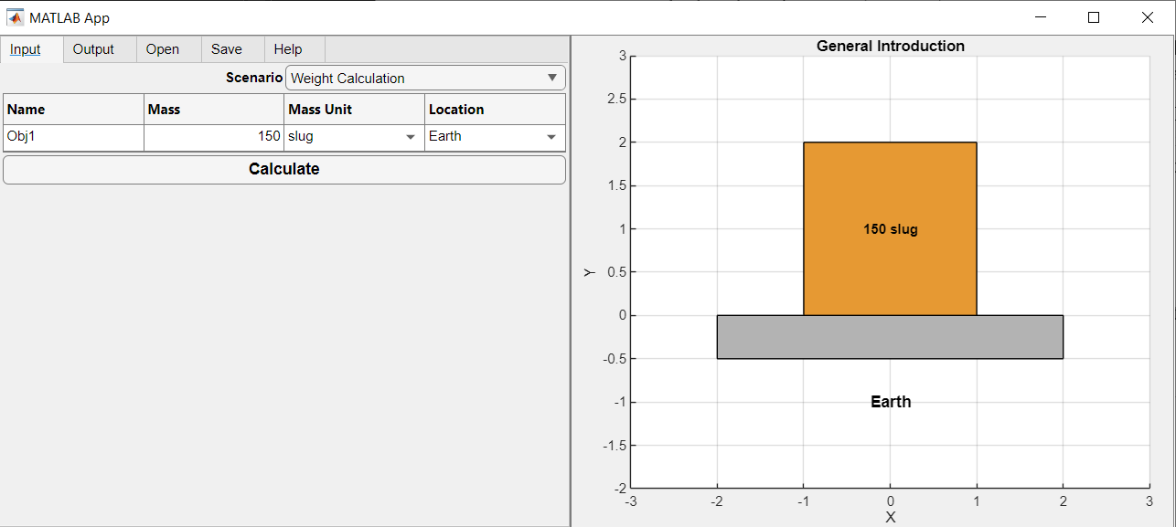
Weight Calculation: Users input the Mass, select its unit, and choose a celestial location (Earth, Moon, or Mars) to automatically apply the correct gravitational acceleration (\(g\)).
To clarify these input requirements, Example 1.1 is considered here. The problem asks for the weight of a \(150\text{ slug}\) mass on Earth, and then the mutual gravitational attraction between this mass and a \(50\text{ slug}\) mass located \(20\text{ ft}\) away. For this example, the input data can be specified in two steps using two different scenarios:
Step 1: Finding the Weight
Scenario = Weight Calculation
Table Input Data: Row 1: Name = Obj1, Mass = 150, Mass Unit = slug, Location = Earth
Step 2: Finding the Gravitational Force
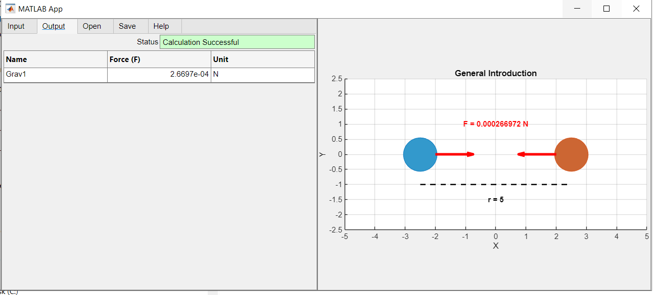
Scenario = Universal Gravitation
Table Input Data: Row 1: Name = Grav1, Mass 1 = 150, Mass 2 = 50, Distance (r) = 20, Unit System = US (slug, ft)
To demonstrate the remaining scenario, consider Example 1.2, where the previously calculated weight of \(4830\text{ lb}\) needs to be converted into newtons (\(\text{N}\)).
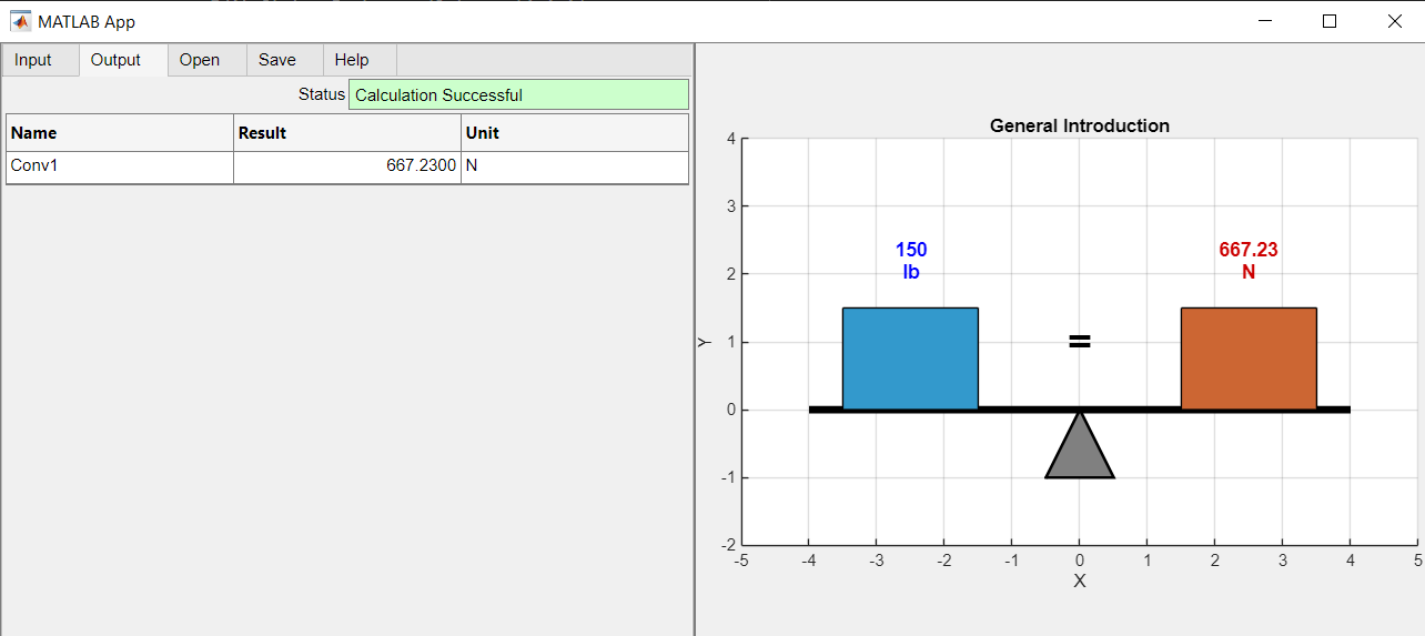
Scenario = Unit Conversion
Table Input Data: Row 1: Name = Conv1, Category = Force, Value = 4830, From Unit = lb, To Unit = N
Understanding the Output Data and Graphical Display
Once the "Calculate" button is clicked (or the Output Tab is selected), the application automatically computes the results using built-in high-precision constants. The results should be interpreted as follows:
Summary Results Panel: Displays the operational status. If the inputs are valid, the status box turns Light Green displaying "Calculation Successful." If there is a missing input (e.g., \(r = 0\)), it turns Light Red with an error message.
Output Table: The exact calculated force (\(F\)), weight (\(W\)), or converted value is displayed alongside its correct unit (e.g., lb or N). This guarantees accurate tracking of significant figures and eliminates manual unit conversion mistakes.
Visual Feedback (UI Axes): In the Output view, the application provides a conceptual physical representation of the mathematical result:
For Weight Calculation: A solid block is rendered resting on a planetary surface with a downward red arrow indicating the weight vector.
For Universal Gravitation: Two scaled spheres are drawn separated by a dashed line of distance \(r\), with inward-pointing red arrows representing the mutual force of attraction.
For Unit Conversion: A dynamic balance scale is drawn. The left tray displays the original value, and the right tray displays the converted value, linked by a large "=" sign, proving visually that different numbers with different units hold the same physical equivalence.
1.5.2 Practice Problems
Problem 1.1
A civil engineering student has a mass of \(160\text{ lb}\) on Earth. (a) Determine his mass in newtons on the surface of the earth. (b) If he travels to the moon, where the acceleration due to gravity is \(g_m = 5.30\text{ ft/s}^2\), determine his mass and his weight on the moon.
(Answers: (a) \(4.97\text{ slugs}\), (b) Mass remains \(4.97\text{ slugs}\), Weight \(= 138\text{ N}\))
Problem 1.2
Unit conversions are a critical source of error in engineering practice. Convert the following quantities into the desired U.S. Customary units: (a) A car is traveling at \(65\text{ mi/h}\). Convert this speed to feet per second (\(\text{ft/s}\)). (Hint: \(1\text{ mi} = 5280\text{ ft}\)). (b) The pressure exerted by a column on a foundation is \(4500\text{ lb/ft}^2\). Convert this pressure to pounds per square inch (psi or \(\text{lb/in}^2\)).
(Answers: (a) \(95.3\text{ ft/s}\), (b) \(31.25\text{ psi}\))
Problem 1.3
Two bridge foundation concrete piers, each with a mass of \(30,000\text{ slugs}\), are located \(60\text{ ft}\) apart (center-to-center). Use the provided user-friendly application to determine the mutual gravitational force of attraction between them. Compare this force to the weight of a single pier.
(Answers: Mutual Force \(= 0.0086\text{ lb}\), Pier Weight \(= 966,000\text{ lb} = 966\text{ kip}\). The mutual attraction is practically negligible).