Force System Resultants & Moments
3.1 Introduction to Moments
When a force is applied to an object, it generates not only a linear motion but also a tendency to rotate about a specific point or axis (Figure 3.1a). This rotational tendency is known as the moment of a force or simply the moment. In some contexts, it may also be referred to as torque. For instance, when pushing on the handle of a door, the force applied at a distance from the hinges creates a moment, causing the door to rotate open. The farther the force is applied from the hinge, the easier it is to open the door.
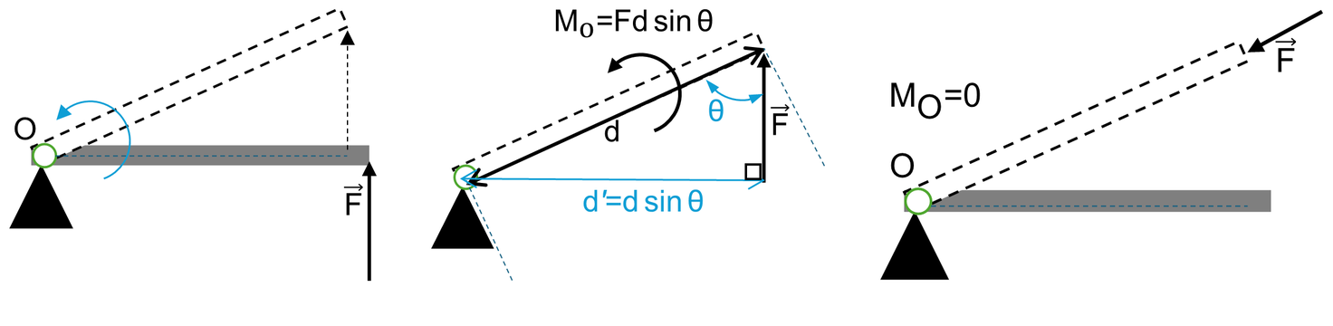
The magnitude of the moment depends on two factors:
- The magnitude of the applied force (\(F\)).
- The perpendicular distance from the point of rotation (\(O\)) to the line of action of the force, commonly referred to as the moment arm (\(d\)).
A larger force or a longer moment arm increases the rotational effect, or moment. However, only the perpendicular component of the force contributes to the rotation. When the force is applied at an angle (\(\theta\)), the effective moment arm becomes smaller, reducing the rotational effect. For example, in Figure 3.1b, when the force is applied at an angle, the moment arm becomes \(d = r\sin\theta\), leading to a smaller moment compared to the case where the force is perpendicular. If the force is applied directly in line with the hinge or pivot (Figure 3.1c), the moment arm becomes zero, and no rotational movement occurs.
Mathematically, the moment can also be expressed in vector form using the cross product:
where \(\vec{r}\) is the position vector from the point of rotation to the point of force application, and \(\vec{F}\) is the applied force vector. Both \(\vec{r}\) and \(\vec{F}\) are vector quantities. A detailed explanation of how to calculate moments using vector formulation is provided in Section 3.4.
Here's an outline of topics covered in this chapter:
- 3.2 Moment of a Force in 2-D Space (Scalar Formulation): Introduces the moment of a force and focuses on calculating moments in a two-dimensional plane using scalar methods.
- 3.3 Cross Product: Explains the use of the cross product in calculating moments for more complex, multi-dimensional systems.
- 3.4 Moment of a Force (Vector Formulation): Discusses the vector formulation of the moment, providing a general method applicable to various engineering problems.
- 3.5 Moment of a Force about a Specified Axis: Examines moments calculated about a specific axis, often necessary for analyzing mechanical systems with rotational components.
- 3.6 Force Couple: Introduces the concept of a force couple, where two equal and opposite forces produce rotation without translation.
- 3.7 Simplification of a Force and Couple System: Details methods to simplify complex force systems by reducing them to an equivalent force-couple system.
- 3.8 User Friendly Application and Practice Problems: Explores computational tools and solved practice problems for 2D and 3D moment systems.
3.2 Moment of a Force in 2-D Space (Scalar Formulation)
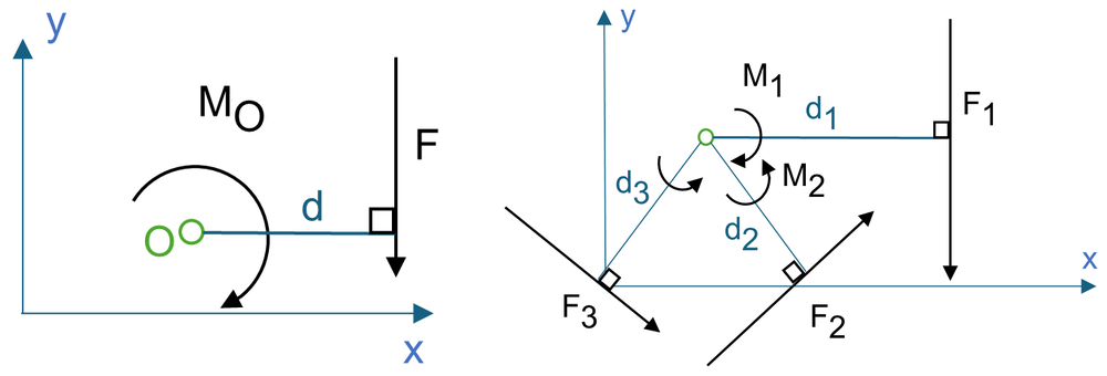
In two-dimensional space, the moment of a force about a point can be described by its magnitude and direction. Consider a force \(\vec{F}\) acting on an object in a plane, with point \(O\) lying in the same plane, as shown in Figure 3.2a. The moment \(M\) about point \(O\), or about an axis passing through \(O\) and perpendicular to the plane, is a vector quantity because it possesses both magnitude and direction.
3.2.1 Magnitude
The magnitude of the moment about point \(O\) is given by:
where \(d\) represents the moment arm, which is the perpendicular distance from point \(O\) to the line of action of the force. The units of moment consist of force multiplied by distance, such as \(\text{N}\cdot\text{m}\) or \(\text{lb}\cdot\text{ft}\).
3.2.2 Direction
The direction of the moment is determined by its moment axis, which is perpendicular to the plane containing the force \(\vec{F}\) and its moment arm \(d\). To establish the moment’s direction, we use the right-hand rule. According to this rule, if you curl the fingers of your right hand in the direction of the rotational tendency (toward the palm), your thumb will point in the direction of the moment vector.
For example, in Figure 3.2a, the moment tends to cause counterclockwise rotation, so the moment vector is directed out of the page. In two-dimensional diagrams, this is typically represented as a curling arrow (Figure 3.2b). In this convention, moments that cause counterclockwise rotation are positive, and those that cause clockwise rotation are negative.
3.2.3 Resultant Moment
In 2D problems, where all forces lie in the \(x\)-\(y\) plane, the resultant moment (\(\sum M_O\)) about point \(O\) (along the \(z\)-axis) can be found by summing the moments caused by each individual force. As a standard convention, counterclockwise moments are considered positive and clockwise moments are considered negative, corresponding to the direction along the positive or negative \(z\)-axis, respectively. Thus, the resultant moment is calculated as:
Here \(n\) is the number of forces applied to the object. If the sum yields a positive scalar, the resultant moment is counterclockwise (out of the page); if it is negative, the resultant moment is clockwise (into the page).
Example 3.1
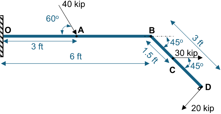
Find the resultant moment of all forces acting on the beam shown in Figure 3.3 about point \(O\).
Solution
Method 1: Moment Arm Approach
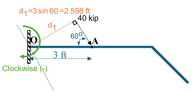
Force 1 (40 kip): Force 1 acts at an angle of \(60^\circ\) relative to the horizontal. As shown in Figure 3.4, the perpendicular distance (\(d_1\)) from Point \(O\) to the line of action of Force 1 is:
Since Force 1 tends to generate a clockwise rotation about point \(O\), its moment (\(M_1\)) is negative:
Force 2 (30 kip): The line of action of Force 2 is parallel to the \(x\)-axis. To determine the perpendicular distance \(d_2\), we extend the line of action and form a right triangle (see Figure 3.5):
Since Force 2 creates a counterclockwise rotation about point \(O\), its moment (\(M_2\)) is positive:
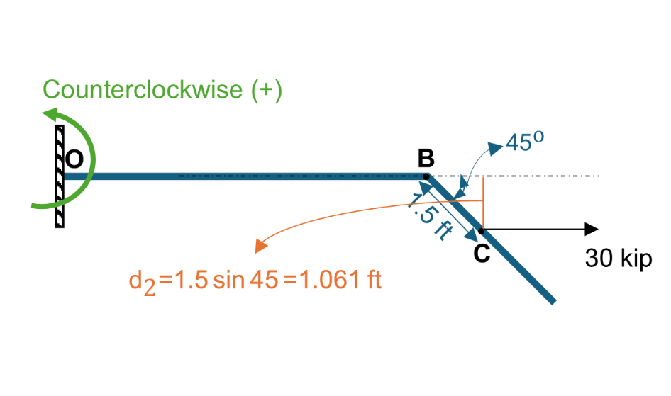
Force 3 (20 kip): Since Force 3 acts along the inclined section of the beam, we determine the perpendicular distance (\(d_3\)) from point \(O\) as illustrated in Figure 3.6:
Since Force 3 tends to rotate the beam clockwise about point \(O\), its moment (\(M_3\)) is negative:
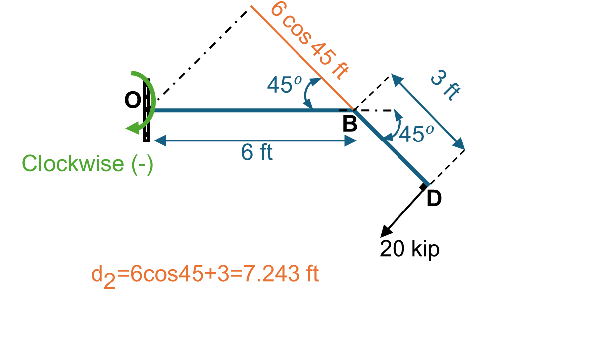
The total net moment at Point \(O\) is calculated by summing the scalar moments:
\(M_{RO} = 216.94\text{ kip}\cdot\text{ft}\quad (\text{clockwise})\)
Method 2: Decomposing Forces into Components
Force 1 (40 kip): Resolving into rectangular components (Figure 3.7):
The line of action of \((F_1)_x\) passes directly through Point \(O\), creating zero moment arm. The vertical component \((F_1)_y\) acts at a distance of \(3\text{ ft}\) causing clockwise rotation:
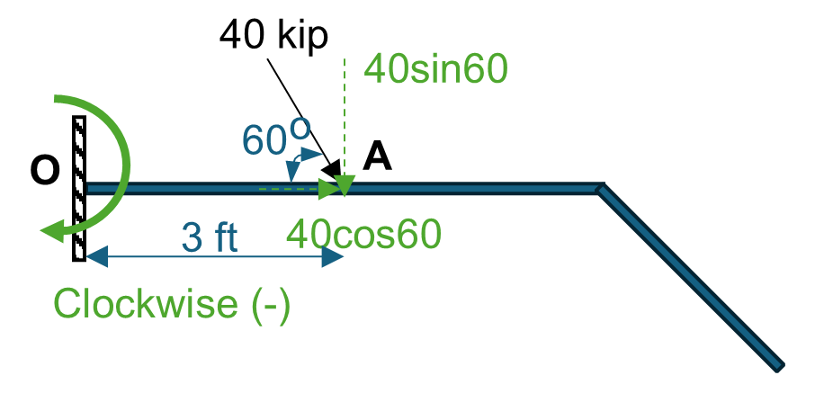
Force 3 (20 kip): Resolving into horizontal and vertical components (Figure 3.8):
The perpendicular distances from Point \(O\) to each component line of action are \(d_x = 6\sin(45^\circ) = 4.243\text{ ft}\) and \(d_y = 3 + 6\cos(45^\circ) = 7.243\text{ ft}\). Both components generate clockwise rotation:
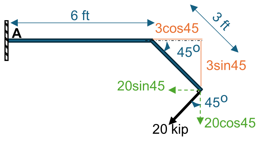
Summing all moments confirms the result from Method 1:
3.3 Cross Product
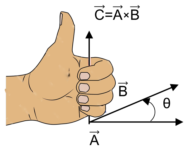
The cross product of two vectors \(\vec{A}\) and \(\vec{B}\) results in a third vector \(\vec{C}\), denoted as:
3.3.1 Magnitude
The magnitude of \(\vec{C}\) is defined as the product of the magnitudes of \(\vec{A}\) and \(\vec{B}\) and the sine of the angle \(\theta\) between their tails (\(0^\circ \le \theta \le 180^\circ\)):
3.3.2 Direction
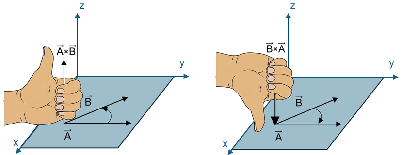
Vector \(\vec{C}\) is perpendicular to the plane containing both \(\vec{A}\) and \(\vec{B}\). Its direction is specified by the right-hand rule: curling fingers from \(\vec{A}\) toward \(\vec{B}\) directs the thumb along \(\vec{C}\):
where \(\hat{u}_C\) is a unit vector pointing in the direction of vector \(\vec{C}\).
3.3.3 Laws of Operation
The cross product is not commutative; reversing the order reverses the sign:
If the cross product is multiplied by a scalar \(a\), it follows the associative law:
The distributive law of addition also applies to vector cross products:
3.3.4 Cartesian Vector Formulation
Equation (3.5) can be employed to calculate the cross product of any pair of Cartesian unit vectors. For instance, to find \(\hat{\imath} \times \hat{\jmath}\), the magnitude of the resultant vector is:
The direction is determined using the right-hand rule, pointing in the \(\hat{k}\) direction, hence:
In a similar manner, the cyclic and reversed cross products are derived:
Crossing any unit vector with itself yields zero: \(\hat{\imath} \times \hat{\imath} = \hat{\jmath} \times \hat{\jmath} = \hat{k} \times \hat{k} = \vec{0}\). A handy memory aid is the counterclockwise circle: crossing adjacent vectors counterclockwise yields the positive third unit vector, while clockwise crossing gives the negative unit vector.
3.3.5 Determinant Formulation (Sarrus' Rule)
Now let’s consider the cross product of two general vectors \(\vec{A}\) and \(\vec{B}\), expressed in Cartesian vector form. The cross product can be computed using a \(3\times 3\) determinant:
Expanding this determinant across the first row yields the component form:
Example 3.2
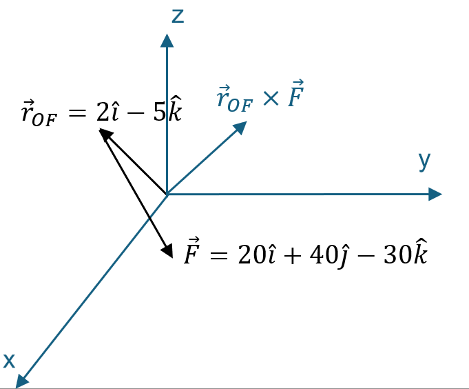
Find the cross product of position vector \(\vec{r}_{OF} = 2\hat{\imath} - 5\hat{k}\) and force vector \(\vec{F} = 20\hat{\imath} + 40\hat{\jmath} - 30\hat{k}\).
Solution
Setting up the \(3\times 3\) determinant:
Expanding by minors:
\(\vec{r}_{OF} \times \vec{F} = 200\hat{\imath} - 40\hat{\jmath} + 80\hat{k}\)
The magnitude of the cross product is:
3.4 Moment of a Force - Vector Formulation
The moment of a force \(\vec{F}\) about a point \(O\), or more specifically about the moment axis passing through \(O\) and perpendicular to the plane containing \(O\) and \(\vec{F}\), can be expressed directly using the vector cross product:
3.4.1 Magnitude of the Moment
From the definition of the cross product, the magnitude of \(\vec{M}_O\) is:
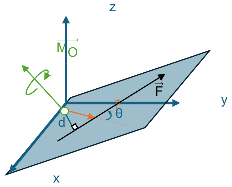
where \(\theta\) is the angle between the tails of \(\vec{r}\) and \(\vec{F}\) (Figure 3.12). The moment arm \(d\) is the perpendicular distance from point \(O\) to the line of action of \(\vec{F}\), where \(d = r\sin\theta\). Hence:
3.4.2 Direction of the Moment
The direction and sense of \(\vec{M}_O\) are determined by the right-hand rule. When the fingers of the right hand are curled in the direction of the rotational tendency, the extended thumb points in the direction of \(\vec{M}_O\), perpendicular to the plane containing \(\vec{r}\) and \(\vec{F}\).
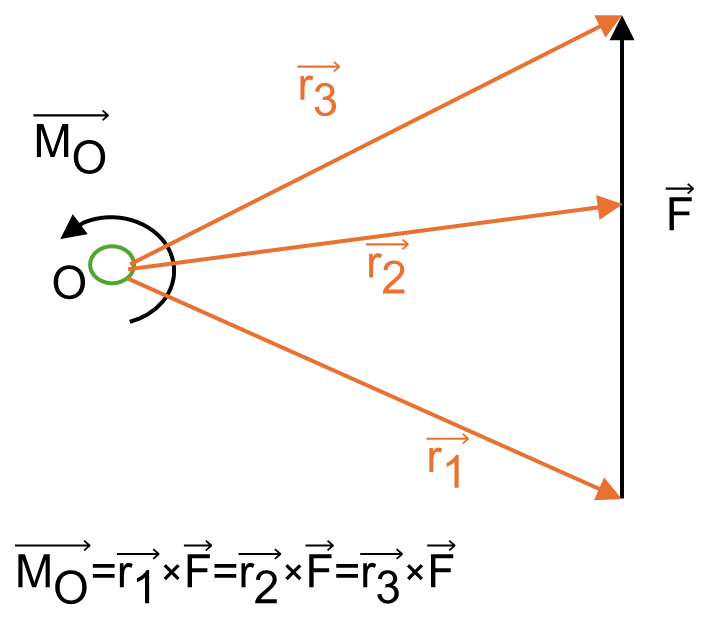
3.4.3 Principle of Transmissibility
According to the principle of transmissibility, the position vector \(\vec{r}\) can extend from point \(O\) to any arbitrary point lying along the line of action of force \(\vec{F}\) (Figure 3.13):
3.4.4 Cartesian Vector Formulation
Expressing \(\vec{r}\) and \(\vec{F}\) in Cartesian components:
The moment vector \(\vec{M}_O\) is computed via the determinant:
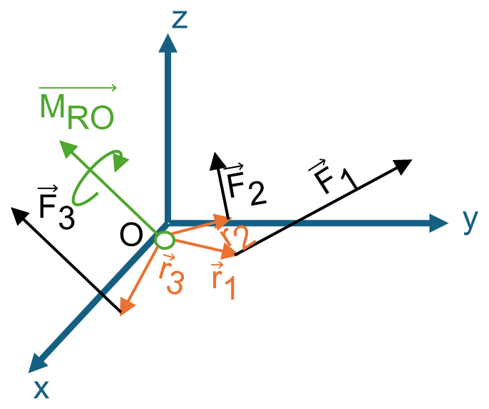
3.4.5 Resultant Moment of a System of Forces
If a body is acted upon by a system of forces, as depicted in Figure 3.14, the resultant moment about point \(O\) is determined by vector summation of individual moment contributions:
Example 3.3
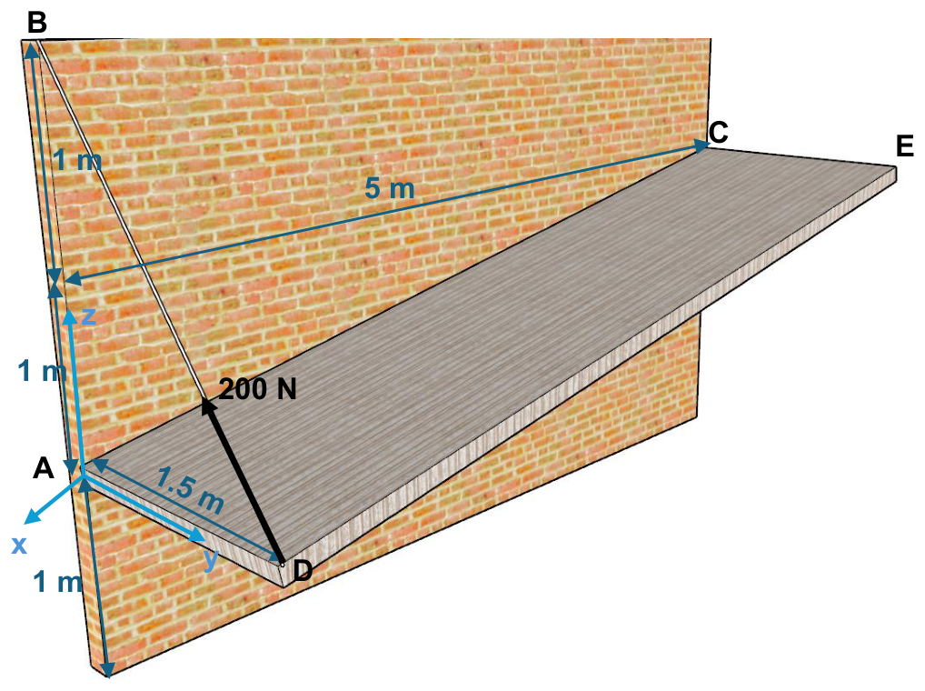
In the system shown in Figure 3.15, the tensile force in the DB cable is \(200\text{ N}\). What is the moment created by the DB cable about Point \(A\)?
Solution
1. Defining Points: The force line of action passes through Points \(D\) and \(B\). Choosing Point \(B\) on the line of action for the position vector from reference Point \(A\):
2. Calculating Position Vector (\(\vec{r}_{AB}\)):
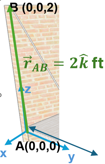
3. Calculating Unit Vector (\(\hat{u}_{DB}\)): The unit vector along the cable from \(D\) to \(B\) is:
4. Force in Vector Form (\(\vec{F}_{DB}\)): Multiplying tensile magnitude by unit vector \(\hat{u}_{DB}\):
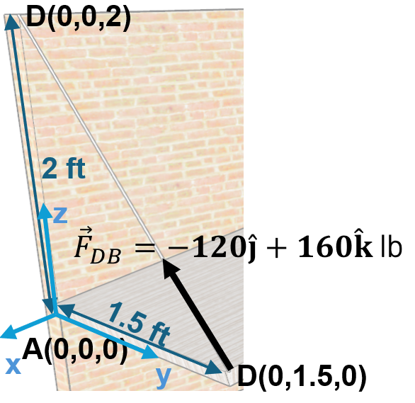
5. Moment about Point \(A\) (\(\vec{M}_A\)):
\(\vec{M}_A = [0(160) - 2(-120)]\hat{\imath} - [0]\hat{\jmath} + [0]\hat{k} = 240\hat{\imath}\text{ N}\cdot\text{m}\)
3.5 Moment of a Force about a Specified Axis
In many engineering applications, it is necessary to determine the moment a force produces about a specific axis. For example, when a force is applied to a door handle, it creates a tendency for the door to rotate about the hinges, which act as the axis passing through point \(O\) (Figure 3.18). However, the door can only rotate about the vertical \(z\)-axis of the hinges. Therefore, the moment that matters is the component along this axis, which can be determined using scalar or vector analysis.
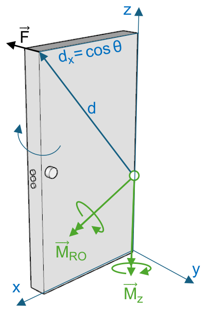
3.5.1 Scalar Analysis
When the perpendicular distance \(d_a\) from the force's line of action to the specified axis can be readily determined, the moment magnitude about axis \(a\) is:
3.5.2 Vector Analysis
Using vector methods, the moment of force \(\vec{F}\) about axis \(a\) is the scalar projection of the moment \(\vec{M}_O\) onto the axis unit vector \(\hat{u}_a\):
where \(\vec{r}\) extends from any point on axis \(a\) to any point on the line of action of \(\vec{F}\). In determinant form:
Example 3.4
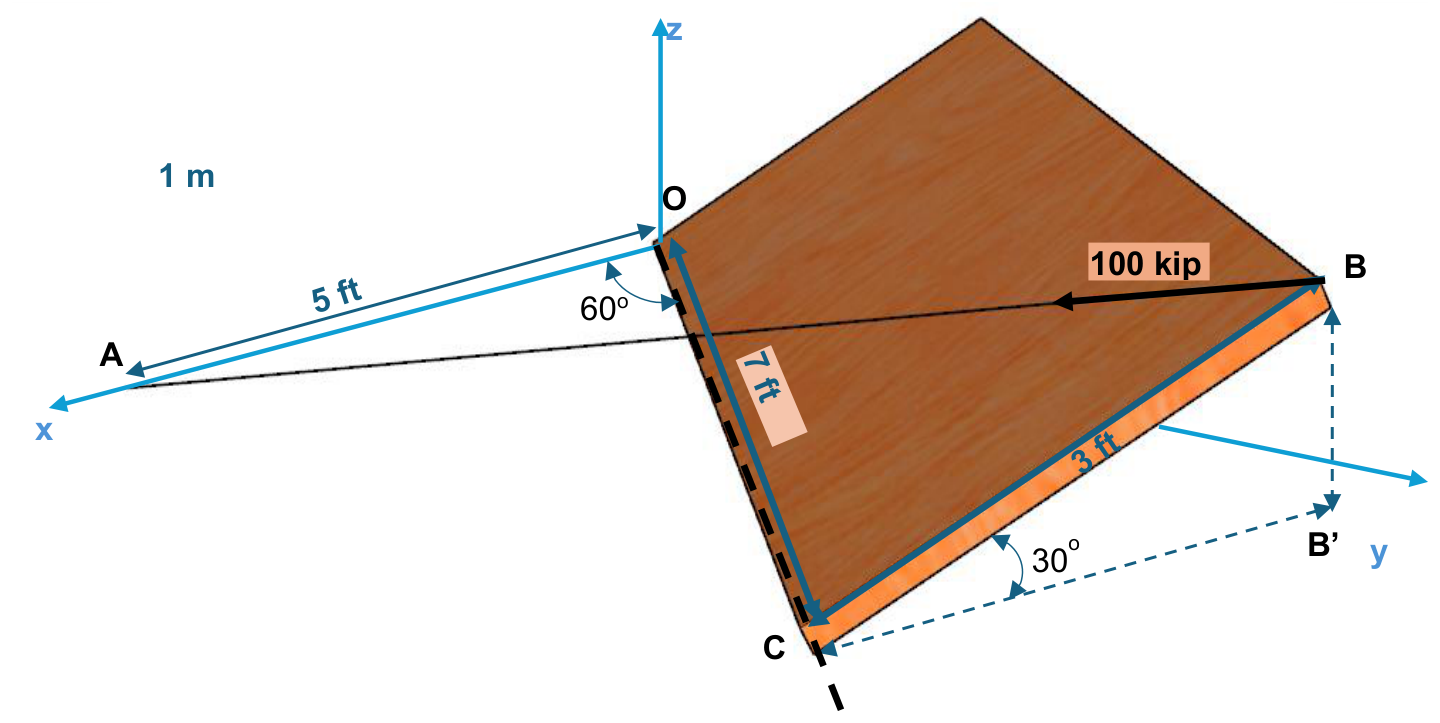
Find the moment created by the BA cable about the OC axis in the system shown in Figure 3.19.
Solution
1. Coordinates of Points:
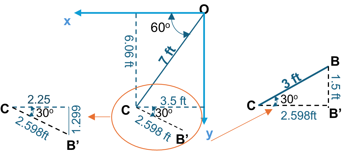
Finding Point \(B\): Using plan projection \(B'\) with \(CB' = 3\cos(30^\circ) = 2.598\text{ ft}\) (Figure 3.20):
\(B = (1.25, 7.36, 3\sin 30^\circ) = (1.25, 7.36, 1.5)\text{ ft}\)
2. Position Vector (\(\vec{r}_{OA}\)):
3. Unit Vector along \(OC\) Axis (\(\hat{u}_{OC}\)):
4. Force Vector (\(\vec{F}_{BA}\)):
5. Moment about \(OC\) Axis (\(M_{OC}\)):
\(M_{OC} = 0.5[0 - 0] - 0.866[5(-17.87) - 0] + 0 = 77.36\text{ kip}\cdot\text{ft}\)
3.6 Moment of a Couple
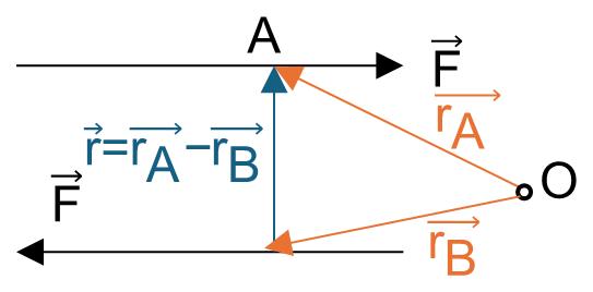
A couple is defined as two parallel forces that have the same magnitude, opposite directions, and are separated by a perpendicular distance \(d\) (Figure 3.21). Since the resultant force of a couple is zero (\(\sum \vec{F} = \vec{0}\)), a couple produces only a tendency for rotation without translation.
3.6.1 Scalar Formulation
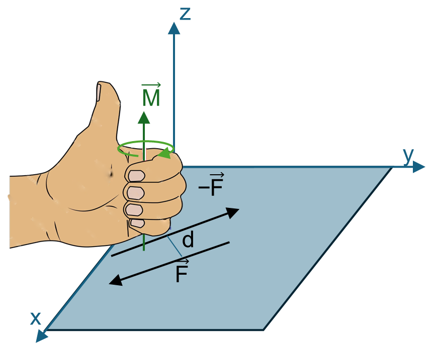
The magnitude of a couple moment \(M\) is defined as the product of the force magnitude \(F\) and the perpendicular distance \(d\) between them:
Its direction is specified by the right-hand rule, perpendicular to the plane containing the two forces (Figure 3.22).
3.6.2 Vector Formulation
The couple moment can also be expressed as a cross product:
where \(\vec{r}\) is a position vector directed from any point on the line of action of \(-\vec{F}\) to any point on the line of action of \(\vec{F}\). The value of \(\vec{M}\) is independent of the reference point, meaning a couple moment is a free vector.
3.6.3 Equivalent Couples
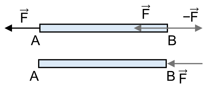
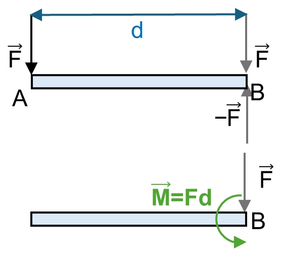
Two couples are equivalent if they produce the same moment magnitude and direction, even if their individual force magnitudes and distances differ (Figure 3.23).
3.6.4 Resultant Couple Moment
Because couple moments are free vectors, multiple couples acting on a body can be added vectorially:
3.7 Simplification of a Force and Couple System
A system of multiple forces and couple moments acting on a rigid body can be simplified by combining all forces into a single resultant force \(\vec{F}_R\) and all moments into a resultant couple moment \(\vec{M}_{RO}\) at a chosen reference point \(O\).
The general equivalent force-couple system at point \(O\) is determined by:
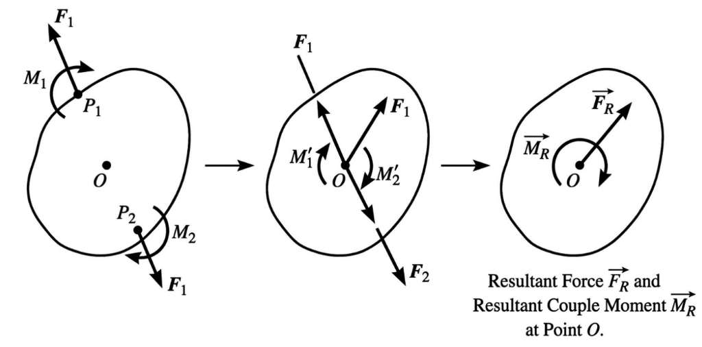
For coplanar force systems in the \(x\)-\(y\) plane, this reduces to three scalar equilibrium relationships: \((F_R)_x = \sum F_x\), \((F_R)_y = \sum F_y\), and \(M_R = \sum F d + \sum M\).
Example 3.5
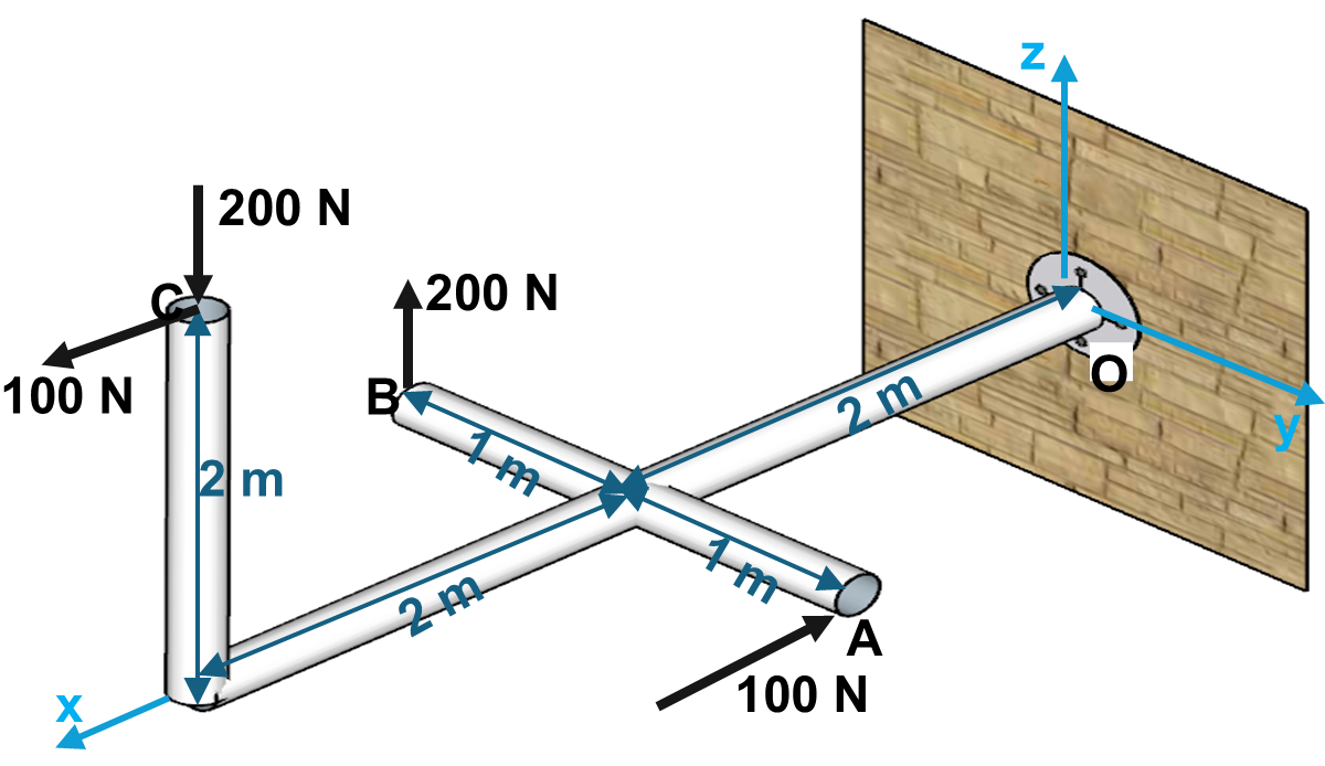
Find the resultant force and moment at point \(O\) in the system shown in Figure 3.26.
Solution
1. Resultant Force: The horizontal forces at \(A\) and \(C\) cancel out (\(100 - 100 = 0\)). Similarly, the vertical forces at \(B\) and \(C\) cancel out (\(200 - 200 = 0\)). Therefore:
2. First Force Couple (Forces at \(A\) and \(C\)):
\(\vec{r}_{CA} = A - C = (2 - 4)\hat{\imath} + (1 - 0)\hat{\jmath} + (0 - 2)\hat{k} = -2\hat{\imath} + \hat{\jmath} - 2\hat{k}\text{ m}\)
\(\vec{M}_1 = \vec{r}_{CA} \times \vec{F}_A = (-2\hat{\imath} + \hat{\jmath} - 2\hat{k}) \times (-100\hat{\imath}) = 200\hat{\jmath} + 100\hat{k}\text{ N}\cdot\text{m}\)
3. Second Force Couple (Forces at \(B\) and \(C\)):
\(\vec{r}_{CB} = B - C = (2 - 4)\hat{\imath} + (-1 - 0)\hat{\jmath} + (0 - 2)\hat{k} = -2\hat{\imath} - \hat{\jmath} - 2\hat{k}\text{ m}\)
\(\vec{M}_2 = \vec{r}_{CB} \times \vec{F}_B = (-2\hat{\imath} - \hat{\jmath} - 2\hat{k}) \times (200\hat{k}) = -200\hat{\imath} + 400\hat{\jmath}\text{ N}\cdot\text{m}\)
4. Total Moment at Point \(O\):
Example 3.6
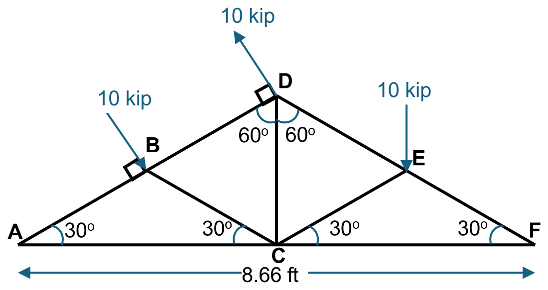
Find the resultant force and moment in the truss system shown in Figure 3.27.
Solution
Step 1: Analyze Force Couple (Points \(B\) and \(D\)): Since triangle \(BCD\) is equilateral, the distance \(BD\) is \(2.5\text{ ft}\):
\(F_{\text{couple}} = 0\)
Step 2: Analyze Force at Point \(E\): The force at \(E\) is directed vertically downward:
Perpendicular distance \(d_{AE}\) from Force at \(E\) to Point \(A\):
\(M_2 = -F \cdot d_{AE} = -(10\text{ kip})(6.495\text{ ft}) = -64.95\text{ kip}\cdot\text{ft}\quad (\text{clockwise})\)
Step 3: Total Resultant Effects:
\(M_{\text{total}} = M_1 + M_2 = 25 - 64.95 = -39.95\hat{k}\text{ kip}\cdot\text{ft}\)
3.8 User Friendly Application and Practice Problems
3.8.1 Description of User Friendly Application
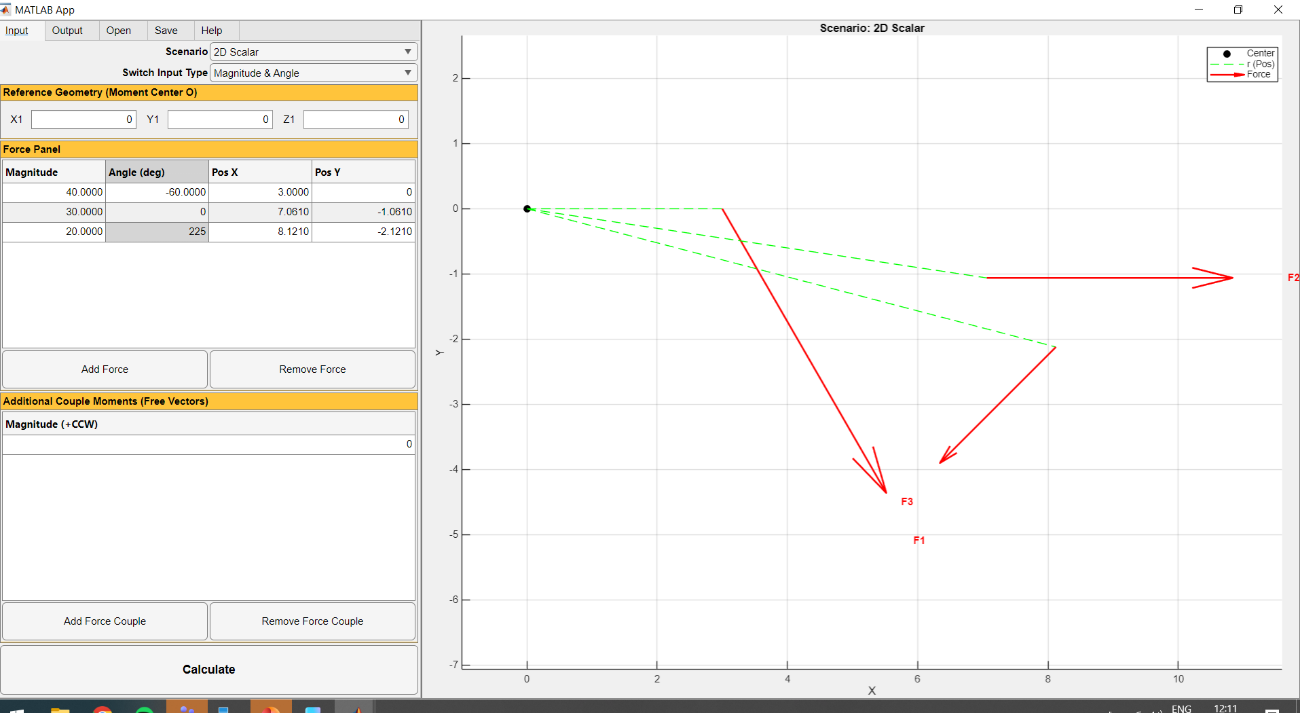
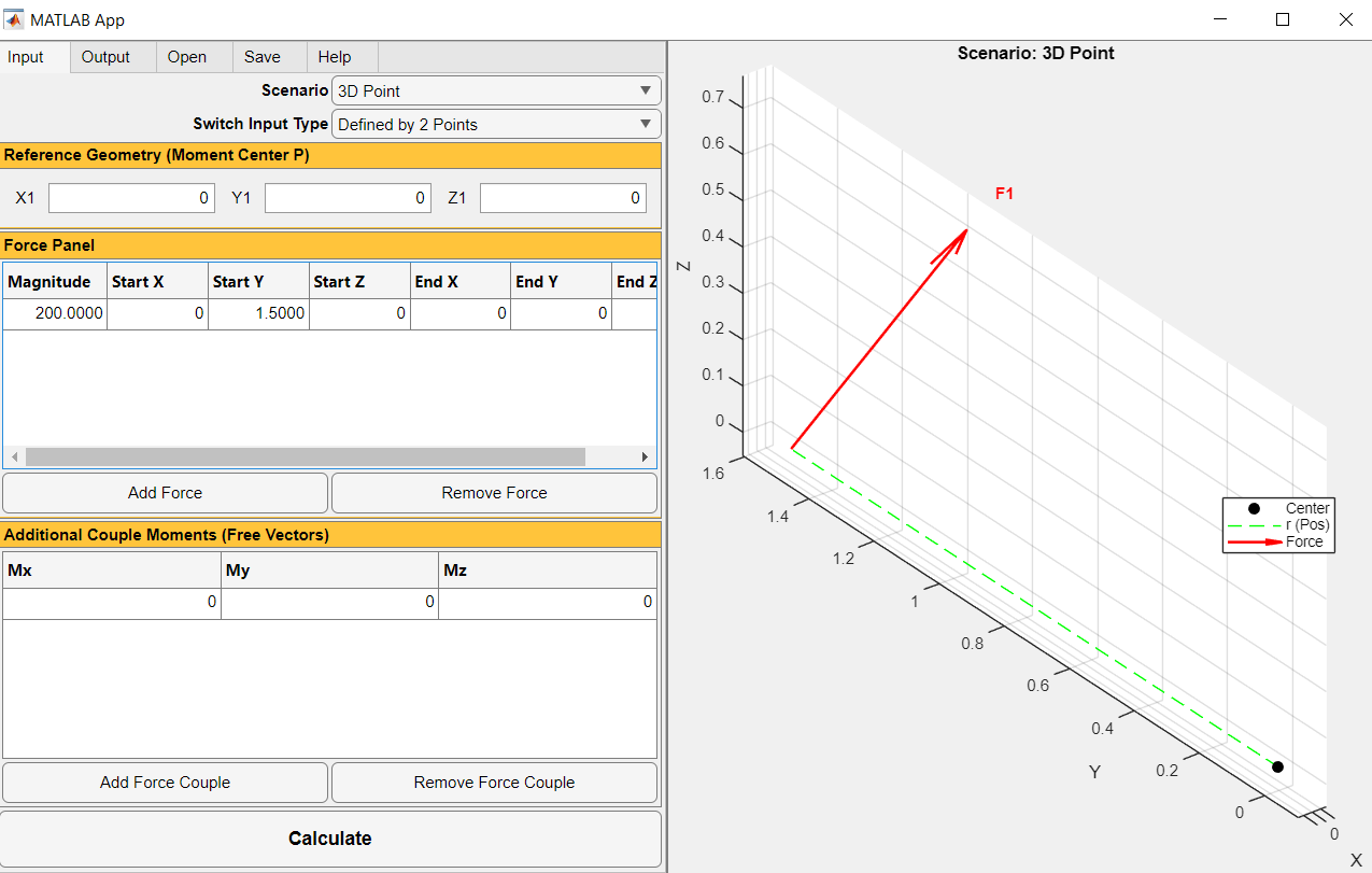
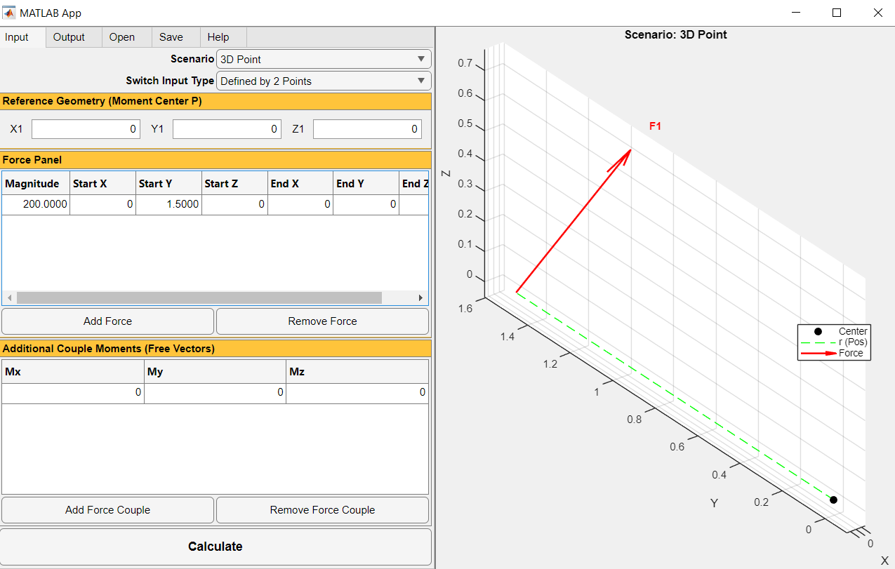
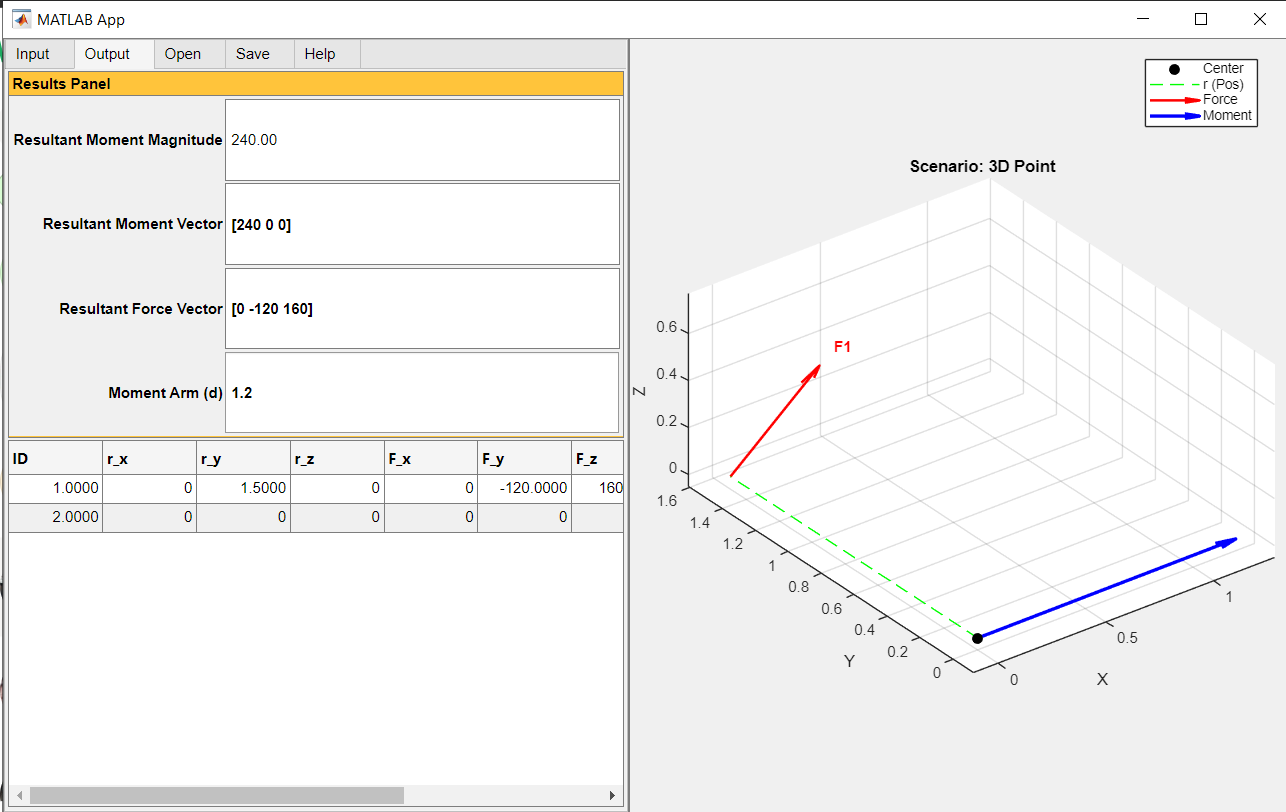
Based on the theories and moment principles presented in Chapter 3, an interactive, user-friendly digital application has been developed with an emphasis on intuitive menu-driven input data, interactive 3D graphical displays of position vectors, force vectors, and resultant moments.
For any 2D or 3D moment calculation problem, the following input parameters are configured:
- (a) Scenario: Select between 2D Scalar (moment about \(z\)-axis, \(M_z\)), 3D Point (moment vector \([M_x, M_y, M_z]\) about reference point \(P\)), or 3D Axis (moment projection along an arbitrary axis defined by two points).
- (b) Reference Geometry: Enter coordinates for the moment center (Point 1 \([X_1, Y_1, Z_1]\)) or the axis of rotation (Point 1 and Point 2).
- (c) Input Type: Choose between Cartesian components \([F_x, F_y, F_z]\) or two coordinate points defining the force's line of action with its magnitude.
- (d) Force Panel: Dynamically add multiple applied forces and couples.
- (e) Free Couple Moments: Directly specify concentrated free couple vectors.
3.8.2 Practice Problems
Problem 3.1
A bracket is subjected to a vertical force \(F_1 = 50\text{ lb}\) applied at \(x = 2\text{ ft}\), \(y = 3\text{ ft}\), and a horizontal force \(F_2 = 30\text{ lb}\) applied at \(x = 4\text{ ft}\), \(y = 1\text{ ft}\). Calculate the resultant scalar moment about the origin \(O(0, 0)\). Use the user-friendly application to verify your solution.
Problem 3.2
A bent pipe assembly is acted upon by a concentrated force \(\vec{F} = (40\hat{\imath} - 20\hat{\jmath} + 50\hat{k})\text{ N}\) applied at point \(B(0.3, 0.4, -0.2)\text{ m}\). Determine the moment vector \(\vec{M}_A\) of this force about point \(A(0.1, 0, 0.2)\text{ m}\) using the Cartesian determinant formulation.
Problem 3.3
A structural frame is loaded by force \(\vec{F} = (150\hat{\imath} + 200\hat{\jmath} - 100\hat{k})\text{ lb}\) applied at \(D(2, 3, 4)\text{ ft}\). Determine the magnitude of the moment projected along an axis passing through \(A(0, 0, 0)\) and \(C(4, 4, 2)\text{ ft}\).
Problem 3.4
A plate is subjected to a system of forces and couple moments. Force 1 = \((50\hat{\imath} - 20\hat{k})\text{ lb}\) acting at \((2, 1, 0)\text{ ft}\). Force 2 = \((-30\hat{\imath} + 40\hat{\jmath} + 10\hat{k})\text{ lb}\) acting at \((0, 2, 2)\text{ ft}\). An additional free couple moment \(\vec{M}_c = (100\hat{\imath} + 50\hat{\jmath})\text{ lb}\cdot\text{ft}\) is applied. Replace this system with an equivalent resultant force and couple moment at the origin.