Equilibrium of Rigid Bodies
Free-Body Diagrams, 2D/3D Support Reactions, and Static Determinacy
4.1 Conditions for Rigid-Body Equilibrium
4.1.1 The Concept of Equilibrium
The concept of equilibrium is fundamental in statics. Think of a bridge, a building, a chair you're sitting on, or even a ladder leaning against a wall. All of these objects are in equilibrium—they are not moving. Statics is the science of determining the forces at play within and upon these stationary objects.
A rigid body is said to be in equilibrium when it remains at rest under the action of all external forces acting on it. (More generally, it could also be moving with a constant velocity, but in statics, we focus exclusively on stationary bodies). This state of rest implies that the body has neither translational acceleration (it's not changing its position) nor angular acceleration (it's not changing its rotation).
From mechanics, we know that any system of external forces and moments acting on a rigid body can be reduced to a single resultant force \(\vec{F}\) and a resultant moment \({\vec{M}}_{O}\) about any arbitrary reference point O. For the body to be in equilibrium, both of these resultant vectors must be zero.
4.1.2 Mathematical Conditions of Equilibrium
The physical requirement of "no acceleration" translates into two core mathematical conditions:
1. Force Equilibrium: The vector sum of all external forces acting on the body must be zero (ensuring no linear acceleration).
Intuition: For every force pushing the object up, there must be an equal force pushing it down. For every force pushing it right, there must be an equal force pushing it left.
2. Moment Equilibrium: The vector sum of the moments of all external forces about any point \(O\) must be zero (ensuring no angular acceleration).
Intuition: Think of a balanced seesaw. A heavier child sitting close to the center (fulcrum) creates a turning effect (a moment). To balance this, a lighter child must sit farther away, creating an equal and opposite turning effect. When all clockwise turning effects perfectly cancel all counter-clockwise turning effects, the seesaw is in rotational equilibrium.
Breaking it Down: From Vectors to Simple Algebra
Working with vectors directly can be complex. We simplify the problem by resolving the force and moment vectors into their scalar components along the x, y, and z axes. This gives us a set of up to six independent, easy-to-solve algebraic equations.
In three-dimensional space, this yields six independent scalar equations, as shown in Table 4.1:
| Translational Equilibrium | Rotational Equilibrium |
|---|---|
$$\sum F_x = 0$$ |
$$\sum M_x = 0$$ |
$$\sum F_y = 0$$ |
$$\sum M_y = 0$$ |
$$\sum F_z = 0$$ |
$$\sum M_z = 0$$ |
These six equations form the theoretical foundation for solving equilibrium problems and determining unknown support reactions.
4.2 Free-Body Diagrams for Rigid Bodies
A Free-Body Diagram (FBD) is a simplified drawing of an object, isolated from its surroundings, showing all the external forces and moments acting upon it. Mastering the FBD is the single most critical step to success in statics. A correct FBD turns a complex physical problem into a straightforward mathematical one.
Steps to Construct a Proper FBD
Isolate the Body: Select the rigid body (or part) you wish to analyze. Conceptually separate it from its surroundings, including supports and adjacent components.
Show All External Forces and Couples:
Applied Loads: These are known forces or moments acting externally.
Body Forces: Typically, gravity, represented by the weight of the object acting through its center of gravity.
Reaction Forces: Unknown support or connection forces that prevent motion. These must be represented according to the type of constraint (see Section 5).
Label Forces and Components:
Represent known quantities with values and directions.
Use variables (e.g., \({R}_{A}\) , \({M}_{O}\) ) for unknown forces or moments.
Include Necessary Geometry:
Show relevant distances and angles required to calculate moments.
Avoid unnecessary structural or visual details that do not contribute to force/moment calculations.
⚠️ Common Pitfall: Internal vs. External Forces
:Do not include internal forces unless analyzing components or substructures.
4.3 Equilibrium in Two Dimensions (2D)
Many engineering problems can be simplified to 2D, where all forces act within a single plane (e.g., the xy-plane).
4.3.1 Scalar Equilibrium Equations in 2D
For any 2D problem, our six general equations reduce to just three independent scalar equations:
Only three independent equations are available, allowing you to solve for up to three unknowns.
4.3.2 Strategic Problem-Solving: Choosing the Right Moment Point
You can sum moments of any point, but a strategic choice can save you a lot of work.
Pro Tip: Always try to sum moments about a point where one or more unknown forces act. Why? Because a force that passes through the moment point has a lever arm of zero and thus creates zero moment. This eliminates that unknown force from your equation, making it much easier to solve.
4.3.3 Support Types and Reaction Forces in 2D
The unknowns in a statics problem are determined by the supports. Each support prevents a specific type of motion by exerting a corresponding reaction force or moment. Understanding how to model these reactions is essential for drawing a correct Free-Body Diagram.
Table 4.2 lists common 2D supports and the reactions they generate:
| Support Type & Symbol | Physical Description | Prevents Motion | Reaction(s) | # of Unknowns |
|---|---|---|---|---|
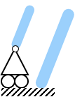
Roller / Rocker / Smooth Surface
|
A wheel or smooth surface that allows free movement parallel to the surface. | Translation perpendicular to the surface. | One force perpendicular to the surface. | 1 |
Cable or Link

|
A cable can only pull; a link can pull or push. | Translation along its axis. | One force along the axis of the cable/link (tension or compression). | 1 |
Pin or Hinge

|
A joint that allows rotation but not translation. Think of a door hinge. | Translation in both horizontal and vertical directions. | Two force components (e.g., \(H_x\) and \(H_y\)). | 2 |
Fixed Support
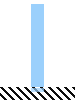
|
A support that is rigidly clamped, preventing all motion. Think of a flagpole cemented in the ground. | All translation (x, y) AND rotation. | Two force components (Fx, Fy) and a couple moment (M). | 3 |
Summary: The Three Fundamental Support Types
While there are many variations, nearly all 2D supports can be classified into three fundamental categories based on how much motion they restrict. This is a key concept for determining the number of unknowns.
| Category | 1. Roller Support (and equivalents) | 2. Hinged Support (or Pin) | 3. Fixed Support |
|---|---|---|---|
| What it Does | Prevents translation in one direction. Allows translation in the other direction and allows free rotation. | Prevents all translation. Allows free rotation. | Prevents all translation and all rotation. |
| Analogy | A car on a flat road. It cannot move down into the ground, but it can roll forward/backward and turn. | A door hinge. The door can swing open (rotate), but it cannot move up, down, or sideways off the hinge. | A light post cemented in the ground. It cannot move or tilt in any direction. |
| Reaction(s) | One force, perpendicular (normal) to the surface. | Two force components (horizontal and vertical). | Two force components AND one moment. |
| Number of Unknowns | 1 Unknown | 2 Unknowns | 3 Unknowns |
| General Drawing |

|

|

|
4.3.4 Static Determinacy and Constraints in 2D
Before starting, we must check if the problem is solvable using statics alone. Let R be the number of unknown support reactions and E be the number of available equilibrium equations (for 2D, E=3).
Statically Determinate: R = E (R = 3). The body is properly constrained, and all unknowns can be found using the equilibrium equations.
Statically Indeterminate: R > E (R > 3). There are more unknowns than equations. The body is "over-constrained." The problem is not solvable with statics alone; methods from "Strength of Materials" (involving material deformation) are needed.
Unstable (Under-constrained): R < E (R < 3). There are not enough supports to prevent all motion. The body will move under a general load.
A Special Case: Improper Constraints: Sometimes, even if R = 3, the body can be unstable due to a poor arrangement of supports.
Concurrent Reactions: All reaction forces intersect at a single point. This arrangement cannot resist a moment about that point, so the body will be free to rotate.
Parallel Reactions: All reaction forces are parallel. This arrangement cannot resist a force perpendicular to the reactions, so the body will be free to translate.
4.3.5 Two-Force and Three-Force Bodies
Recognizing these common patterns can greatly simplify your analysis.
Two-Force Body: An object subjected to forces at only two points. For the body to be in equilibrium, these two forces must be:
Equal in magnitude.
Opposite in direction.
Collinear (acting along the same line connecting the two points).This is why links and cables always have a force directed along their axis.
Three-Force Body: An object subjected to forces at only three points. For the body to be in equilibrium, the lines of action of the three forces must either:
Be concurrent (intersect at a single point), OR
Be parallel.
Knowing this allows you to use geometry and trigonometry (Law of Sines) as a quick alternative to solving the full equilibrium equations.
Example 4.1
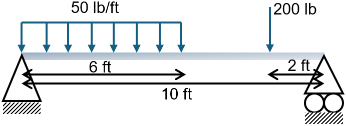
A horizontal beam of length \(10\text{ ft}\) is supported by a pin at point \(A\) (\(x=0\)) and a roller at point \(B\) (\(x=10\text{ ft}\)). The beam is subjected to a uniform distributed load of \(50\text{ lb/ft}\) starting from \(x=0\) to \(x=6\text{ ft}\), and a downward point load of \(200\text{ lb}\) at \(x=8\text{ ft}\). Determine the support reactions at \(A\) and \(B\).
Solution
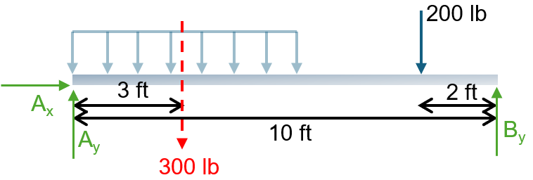
First, draw the free-body diagram (FBD) of the beam, replacing the supports with their respective reaction forces (Figure 4.2):
1. Equivalent Point Load for the Distributed Load:
The location of the equivalent concentrated load acts at the centroid of the rectangular loading: \(\bar{x} = 6/2 = 3\text{ ft}\) from point \(A\).
2. Moment Equilibrium about Point A (\(\sum M_A = 0\)):
\(-900 - 1600 + 10 B_y = 0 \implies B_y = 250\text{ lb}\)
3. Force Equilibrium (\(\sum F_x = 0\) and \(\sum F_y = 0\)):
\(\sum F_y = 0 \implies A_y - 300 - 200 + B_y = 0\)
\(A_y - 500 + 250 = 0 \implies A_y = 250\text{ lb}\)
Answers: \(A_x = 0\), \(A_y = 250\text{ lb}\) (\(\uparrow\)), \(B_y = 250\text{ lb}\) (\(\uparrow\)).
Example 4.2
An L-shaped rigid bracket is firmly fixed to a wall at origin \(A(0, 0)\). The vertical segment extends from \((0, 0)\) to \((0, 6\text{ ft})\), and the horizontal segment extends to \((8\text{ ft}, 6\text{ ft})\). A downward point load of \(150\text{ lb}\) is applied at the free tip \((8\text{ ft}, 6\text{ ft})\). Additionally, a counterclockwise couple moment of \(500\text{ lb}\cdot\text{ft}\) is applied at the tip. Determine the reaction forces and reaction couple moment at the fixed support \(A\).
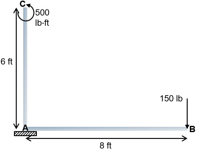
Solution
The free-body diagram replaces the fixed support with two reaction force components (\(A_x, A_y\)) and a reaction couple moment (\(M_A\)), as shown in Figure 4.4:
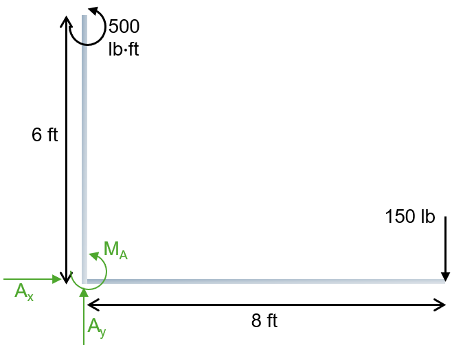
1. Force Equilibrium (\(\sum F_x = 0\) and \(\sum F_y = 0\)):
\(\sum F_y = 0 \implies A_y - 150\text{ lb} = 0 \implies A_y = 150\text{ lb}\)
2. Moment Equilibrium about Support A (\(\sum M_A = 0\)):
\(M_A + 500 - 1200 = 0 \implies M_A = 700\text{ lb}\cdot\text{ft}\)
Answers: \(A_x = 0\), \(A_y = 150\text{ lb}\) (\(\uparrow\)), \(M_A = 700\text{ lb}\cdot\text{ft}\) (counterclockwise \(\circlearrowleft\)).
Example 4.3
A horizontal boom of length \(10\text{ ft}\) and weight \(200\text{ lb}\) (acting at its midpoint, \(x=5\text{ ft}\)) is pinned to a vertical wall at point \(A(0, 0)\). It is supported by a weightless hydraulic cylinder attached to the boom at point \(B(6\text{ ft}, 0)\) and pinned to the wall at point \(C(0, -8\text{ ft})\). A payload of \(500\text{ lb}\) hangs from the free end \(D(10\text{ ft}, 0)\). Determine the force exerted by the hydraulic cylinder and the reaction forces at pin \(A\).
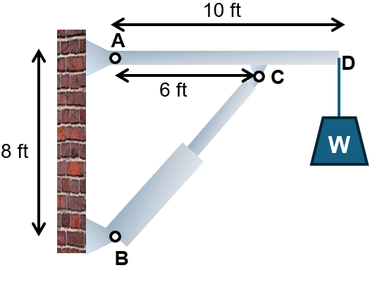
Solution
The hydraulic cylinder connects two pins without intermediate transverse loads, acting as a two-force member along line \(BC\). The free-body diagram of the boom replaces cylinder \(BC\) and pin \(A\) with their reaction forces (Figure 4.6):
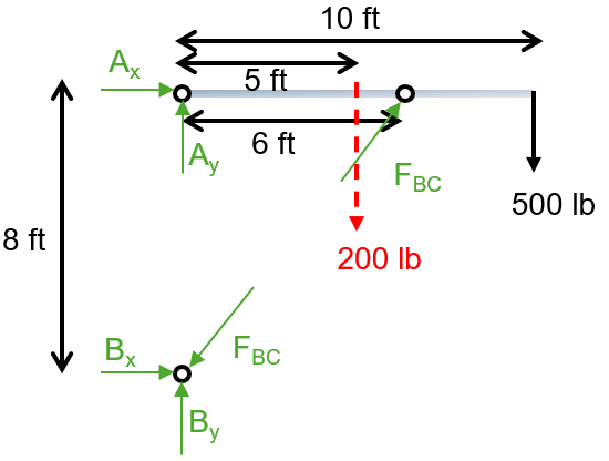
1. Geometry of the Two-Force Member: The slope triangle for \(BC\) has a horizontal run of \(6\text{ ft}\) and a vertical rise of \(8\text{ ft}\). The hypotenuse is \(L_{BC} = \sqrt{6^2 + 8^2} = 10\text{ ft}\). The force components acting on the boom at point \(B\) are:
\(B_y = F_{BC,y} = F_{BC}\left(\frac{8}{10}\right) = 0.8 F_{BC}\)
2. Moment Equilibrium about Pin A (\(\sum M_A = 0\)):
\((0.8 F_{BC})(6) - 1000 - 5000 = 0\)
\(4.8 F_{BC} = 6000 \implies F_{BC} = 1250\text{ lb}\text{ (compression)}\)
Computing the cylinder force components:
\(F_{BC,y} = 0.8(1250\text{ lb}) = 1000\text{ lb}\)
3. Force Equilibrium (\(\sum F_x = 0\) and \(\sum F_y = 0\)):
\(\sum F_y = 0 \implies A_y + F_{BC,y} - 200 - 500 = 0\)
\(A_y + 1000 - 700 = 0 \implies A_y = -300\text{ lb}\text{ (points down, }\downarrow\text{)}\)
Answers: Cylinder force \(F_{BC} = 1250\text{ lb}\) (compression), pin reactions \(A_x = -750\text{ lb}\) (\(\leftarrow\)), \(A_y = -300\text{ lb}\) (\(\downarrow\)).
4.4 Equilibrium in Three Dimensions (3D)
3D problems use the same principles, but require more careful bookkeeping and vector mathematics.
4.4.1 Equilibrium Equations in 3D
We use all six scalar equilibrium equations:
Here, using vector notation is often easier. You represent forces as Cartesian vectors, \(\vec{F} = F_x\hat{\imath} + F_y\hat{\jmath} + F_z\hat{k}\), and compute moments using the cross product, \(\vec{M} = \sum (\vec{r} \times \vec{F})\).
4.4.2 Support Types and Reactions in 3D
The number of unknowns increases as supports can constrain motion in more ways.
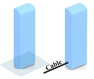
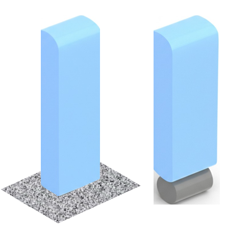
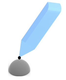
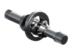
| Support Type | Number of Reaction Components | Constraints Provided |
|---|---|---|
Smooth Surface, Cable
|
1 | One translational constraint |
Roller on Rough Surface
|
2 | Two translational constraints |
Ball-and-Socket Joint
|
3 | All three translational directions |
Universal Joint
|
4 | 3 translations + 1 rotation |
Hinge or Bearing
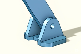
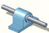
|
5 | 3 translations + 2 rotations |
Fixed Support
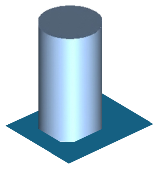
|
6 | 3 translations + 3 rotations (fully constrained) |
4.4.3 Static Determinacy in 3D
The same principle applies, but now we have \(E = 6\) equations.
Determinate: \(R = 6\)
Indeterminate: \(R > 6\)
Unstable: \(R < 6\)
Improper Geometry: \(R = 6\) but reaction lines are concurrent or parallel \(\rightarrow\) system is unstable despite proper count.
Example 4.4
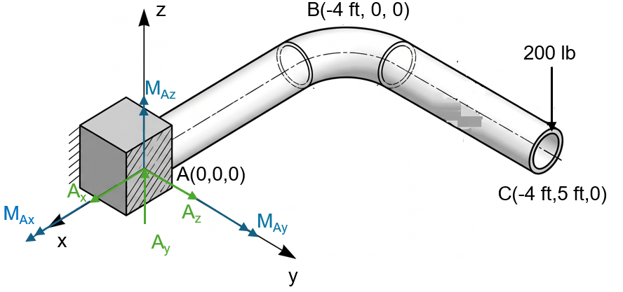
A bent pipe assembly is fixed at origin \(A(0, 0, 0)\). The pipe consists of two straight segments: Segment 1 along the x-axis from \(A(0, 0, 0)\) to \(B(4\text{ ft}, 0, 0)\), and Segment 2 parallel to the y-axis from \(B(4\text{ ft}, 0, 0)\) to \(C(4\text{ ft}, 5\text{ ft}, 0)\). A vertical downward force \(\vec{F} = -200\hat{k}\text{ lb}\) acts at the free tip \(C(4\text{ ft}, 5\text{ ft}, 0)\). Calculate the reaction forces and reaction moments at the fixed support \(A\).
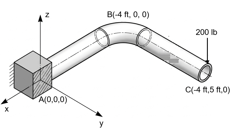
Solution
The free-body diagram replaces the fixed base with 3 reactive force components (\(\vec{A} = A_x\hat{\imath} + A_y\hat{\jmath} + A_z\hat{k}\)) and 3 reactive couple moments (\(\vec{M}_A = M_{Ax}\hat{\imath} + M_{Ay}\hat{\jmath} + M_{Az}\hat{k}\)), as shown in Figure 4.8:
1. Force Equilibrium (\(\sum \vec{F} = \vec{0}\)):
\(\sum F_y = 0 \implies A_y = 0\)
\(\sum F_z = 0 \implies A_z - 200\text{ lb} = 0 \implies A_z = 200\text{ lb}\)
2. Moment Equilibrium about Origin A (\(\sum \vec{M}_A = \vec{0}\)):
The position vector from support \(A\) to point of force application \(C\) is \(\vec{r}_{AC} = 4\hat{\imath} + 5\hat{\jmath}\text{ ft}\). The moment produced by force \(\vec{F} = -200\hat{k}\text{ lb}\) is:
\(= 4(-200)(\hat{\imath} \times \hat{k}) + 5(-200)(\hat{\jmath} \times \hat{k})\)
\(= -800(-\hat{\jmath}) - 1000(\hat{\imath}) = -1000\hat{\imath} + 800\hat{\jmath}\text{ lb}\cdot\text{ft}\)
Applying moment equilibrium \(\vec{M}_A + (\vec{r}_{AC} \times \vec{F}) = \vec{0}\):
\(M_{Ax} - 1000 = 0 \implies M_{Ax} = 1000\text{ lb}\cdot\text{ft}\)
\(M_{Ay} + 800 = 0 \implies M_{Ay} = -800\text{ lb}\cdot\text{ft}\)
\(M_{Az} = 0\)
Answers: Reaction forces: \(\vec{A} = 200\hat{k}\text{ lb}\). Reaction moments: \(\vec{M}_A = 1000\hat{\imath} - 800\hat{\jmath}\text{ lb}\cdot\text{ft}\).
4.5 User Friendly Application and Practice Problems
4.5.1 Description of User Friendly Application
Input Data Requirements
Based on the theories presented in the previous sections of Chapter 4, a user-friendly application has been developed with an emphasis on “user-friendly tabular INPUT data”, smart 3D geometry rendering, and visually intuitive Free-Body Diagrams (FBD). The outputs for rigid body EQUILIBRIUM reactions are explained in this section.
For any rigid body equilibrium problem, the following input data are required:
Scenario = {2D Beam, 2D Rigid Body, 3D Rigid Body}
Geometry Data = Depending on the scenario, either a simple "Beam Length" is entered (for 2D Beam), or the "Geometry" table is used to define the Start and End coordinates of the rigid body segments (for 2D/3D Rigid Bodies).
Table Input Data = Two dynamic tables generate the following columns to define the system:
Supports Table: Users specify the Name, Type (e.g., Pin, Roller, Fixed, Ball-and-Socket), Axis orientation, and Coordinates. The program automatically identifies the Constrained DOFs and draws grey dashed arrows on the FBD to show the unknown reactions.
Loads Table: Users specify the Applied Forces, Moments, or Distributed Loads, along with their locations and values.
To clarify the input data requirements, the 2D Beam problem shown in Example 1 (a 10 ft beam with a distributed load and a point load) is considered here. For this specific example, the input data can be specified as:
Scenario = 2D Beam
Beam Length (L) = 10
Supports Table Input Data:
Row 1 (Pin Support): Name = Sup1, Type = Pin, Loc (x) = 0
Row 2 (Roller Support): Name = Sup2, Type = Roller, Loc (x) = 10
Loads Table Input Data:
Row 1 (Distributed Load): Name = w1, Type = Dist. Load, Loc (x) = 0, Value 1 = 50, Value 2 = 50, Length = 6
Row 2 (Point Force): Name = F1, Type = Point Force, Loc (x) = 8, Value 1 = 200, Angle = 270 (pointing straight down)
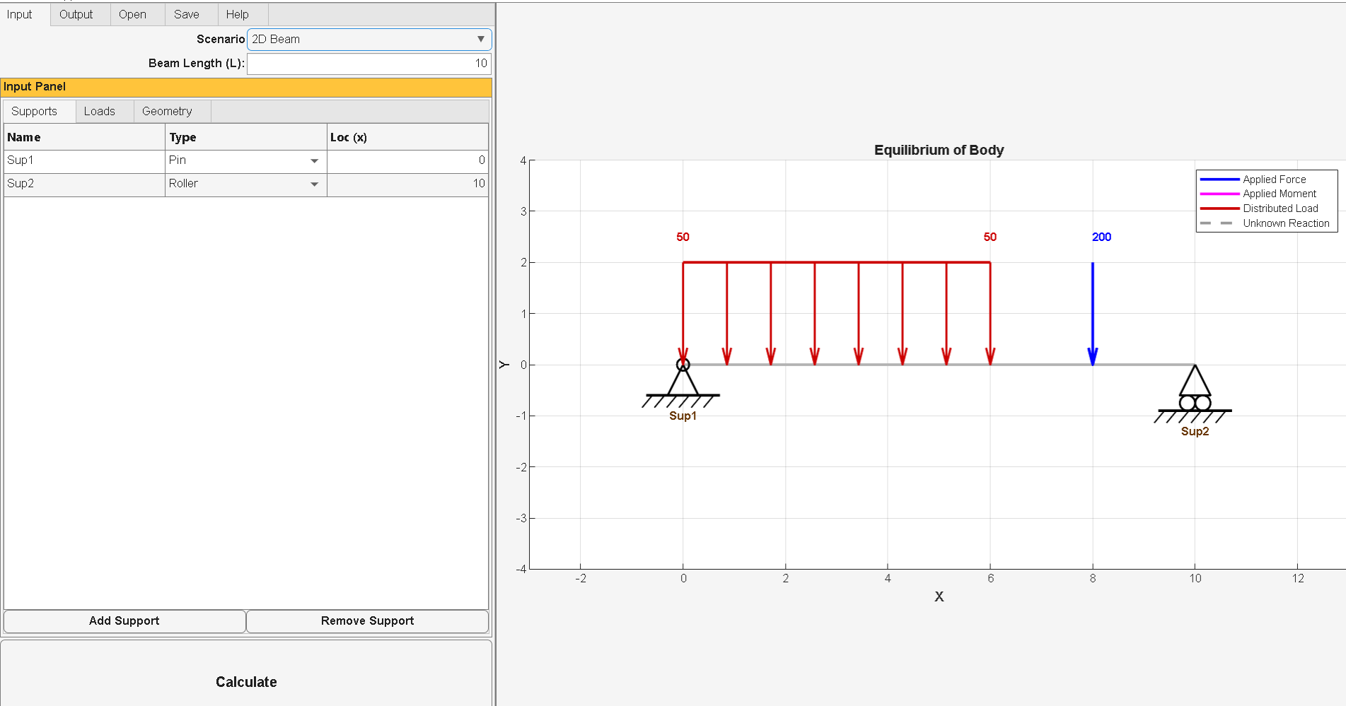
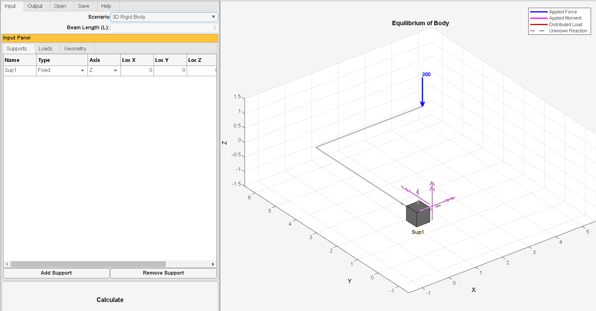
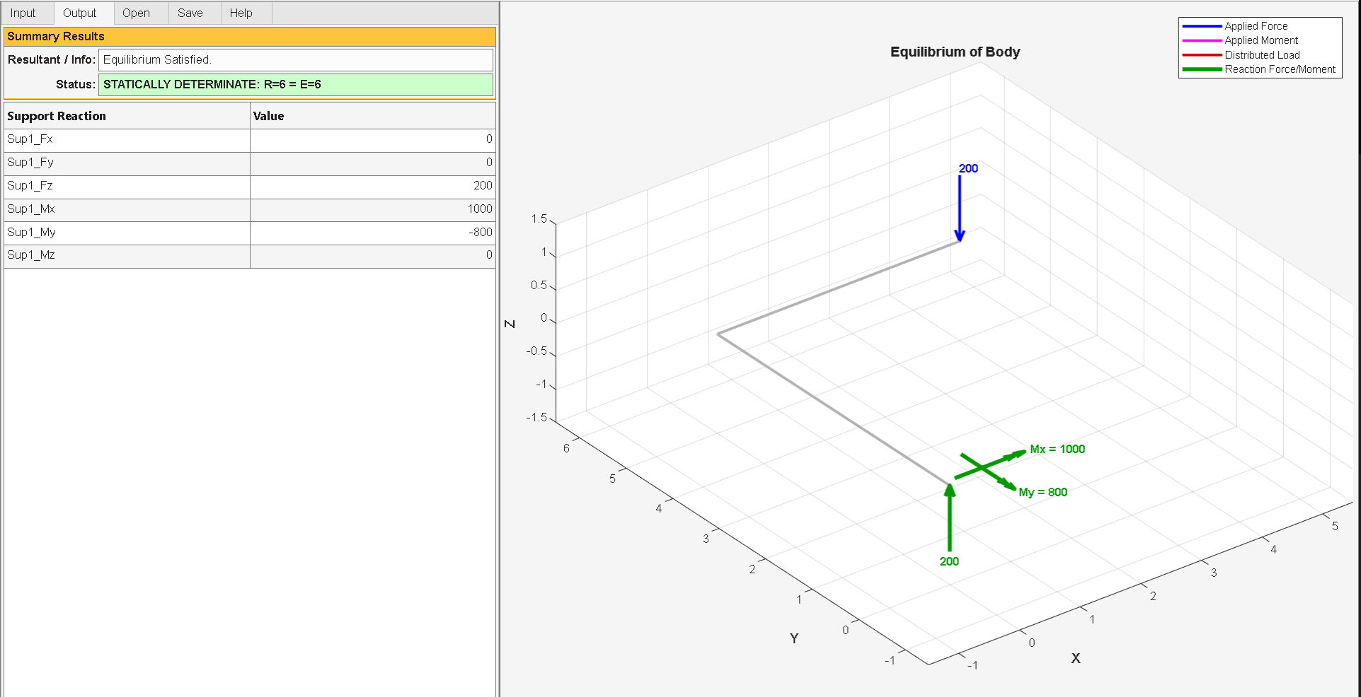
Another example, the 3D bent pipe problem shown in Example 3, is considered here. The pipe is fixed at the origin and subjected to a 200 lb downward force at its tip. For this specific 3D example, the input data can be specified as:
Scenario = 3D Rigid Body
Geometry Table Input Data (Auto-snap active):
Row 1 (Segment 1): Name = Seg1, Start (X,Y,Z) = 0, 0, 0 | End (X,Y,Z) = 0, 5, 0
Row 2 (Segment 2): Name = Seg2, Start (X,Y,Z) = 0, 5, 0 | End (X,Y,Z) = 4, 5, 0
Supports Table Input Data:
Row 1 (Fixed Wall): Name = Sup1, Type = Fixed, Axis = Z, Loc (X,Y,Z) = 0, 0, 0
Loads Table Input Data:
Row 1 (Applied Force): Name = F1, Type = Point Force, Loc (X,Y,Z) = 4, 5, 0 | Fx = 0, Fy = 0, Fz = -200
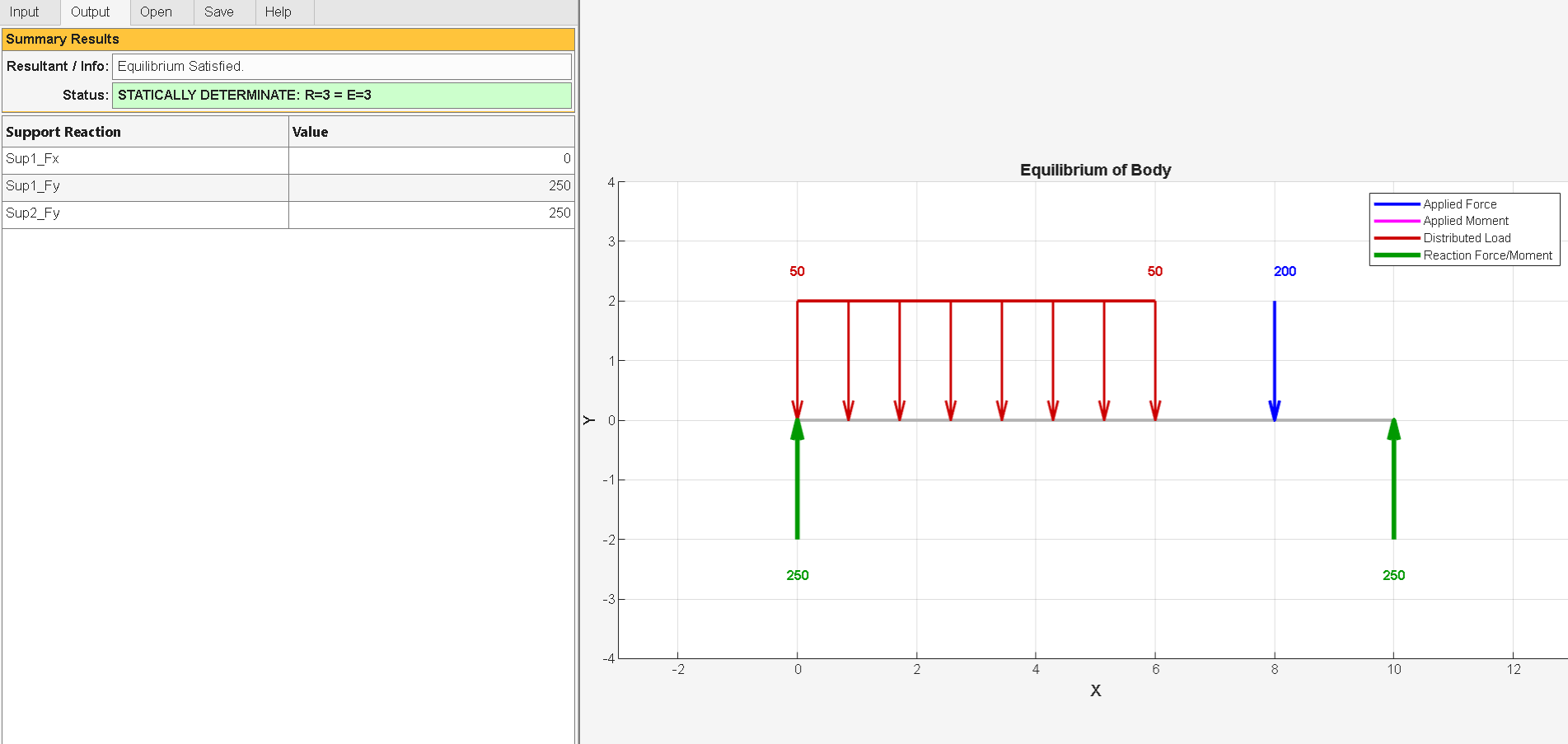
Understanding the Output Data and Graphical DisplayOnce the "Calculate" button is clicked (or the Output Tab is selected), the app automatically solves the rigid body equilibrium matrix equations. The results should be interpreted as follows:
Summary Results Panel: Displays the operational status. If the equilibrium equations are successfully solved and the body is properly constrained ( \(R=E\) ), the status box turns Green displaying "STATICALLY DETERMINATE". If there are too many supports ( \(R>E\) ), it turns Yellow ("STATICALLY INDETERMINATE"). If there are too few supports or improper constraints (e.g., parallel reaction lines resulting in a determinant of zero), it turns Red displaying "UNSTABLE" along with an explanatory error message.
Output Table (Reactions): This table is populated with the exact calculated force and moment magnitudes for each constrained Degree of Freedom (e.g., Sup1_Fx, Sup1_Mz).
Visual Feedback (UI Axes): In the Output view, the original applied active loads are rendered as solid Blue arrows (or magenta for moments). The newly calculated reactive forces and moments are rendered as solid Dark Green arrows, complete with their numerical magnitudes attached to the vectors. The initial grey dashed lines disappear, leaving students with a mathematically verified, complete Free-Body Diagram.
4.5.2 Practice Problems
Practice Problem 4.1
A \(15\text{ ft}\) simply supported beam has a pin at \(x=0\) and a roller at \(x=15\text{ ft}\). A point load of \(600\text{ lb}\) acts at \(x=5\text{ ft}\) at an angle of \(60^\circ\) below the horizontal (pointing right and down). Determine the support reactions.
Practice Problem 4.2
A 2D rigid plate has a pin support at \((0, 0)\) and a cable attached at \((10\text{ ft}, 0)\) pulling vertically upwards. A clockwise moment of \(-1200\text{ lb}\cdot\text{ft}\) is applied at the center \((5\text{ ft}, 5\text{ ft})\), and a point force of \(400\text{ lb}\) acts downwards at \((10\text{ ft}, 5\text{ ft})\). Find the tension in the cable and the pin reactions.
Practice Problem 4.3
A 3D boom system is supported by a ball-and-socket joint at the origin \((0, 0, 0)\). Two cables hold the boom: a roller constraint preventing Z-motion at \((6\text{ ft}, 0, 0)\) and a roller constraint preventing Y-motion at \((6\text{ ft}, 0, 0)\). A force of \(\vec{F} = -100\hat{\imath} - 50\hat{\jmath} - 300\hat{k}\text{ lb}\) acts at \((6\text{ ft}, 0, 0)\). Determine the reaction forces.
Practice Problem 4.4
A \(20\text{ ft}\) long horizontal beam is supported by a pin at \(x=4\text{ ft}\) and a roller at \(x=16\text{ ft}\). It carries a uniform distributed load of \(100\text{ lb/ft}\) over its entire length (from \(x=0\) to \(x=20\text{ ft}\)), and a concentrated clockwise couple moment of \(800\text{ lb}\cdot\text{ft}\) applied at the right tip (\(x=20\text{ ft}\)). Determine the reaction forces at the pin and roller.
Practice Problem 4.5
A rigid L-shaped lever is pinned at the origin \((0, 0)\). A horizontal pushing force of \(50\text{ lb}\) acts to the left (\(-x\) direction) at coordinates \((0, 12\text{ in})\). A vertical cable pulls upwards (\(+y\) direction) at coordinates \((10\text{ in}, 0)\). Determine the tension in the cable required to maintain equilibrium, and the \(x\) and \(y\) reaction components at the pin.
Practice Problem 4.6
A uniform rectangular steel plate weighing \(120\text{ lb}\) lies in the horizontal \(x-y\) plane. Its corners are located at \((0, 0, 0)\), \((6\text{ ft}, 0, 0)\), \((6\text{ ft}, 4\text{ ft}, 0)\), and \((0, 4\text{ ft}, 0)\). The plate is supported by a ball-and-socket joint at origin \((0, 0, 0)\) and a hinge at \((0, 4\text{ ft}, 0)\) aligned with the y-axis. A vertical cable holds the corner \((6\text{ ft}, 4\text{ ft}, 0)\) to the ceiling, providing a force purely in the \(+z\) direction. Determine the tension in the vertical cable. (Hint: Sum moments about the y-axis to bypass unknown reactions at the origin and hinge).